Electronic design automation (EDA) software
Modern EDA tools for PCB and electronics design
Modern EDA tools for PCB and electronics design
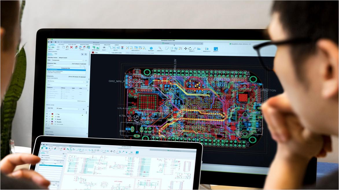
Electronic design automation (EDA) software helps engineers design and validate electronic systems faster. Autodesk Fusion delivers EDA tools for schematics, PCB layout, simulation, and electronics‑to‑mechanical collaboration.
What is electronic design automation (EDA)?
What is electronic design automation (EDA)?
Electronic design automation (EDA), also known as electronic design automation software, is a category of software used to design and develop electronic systems such as printed circuit boards (PCBs) and electronic assemblies. EDA tools automate critical stages of the electronics design process, including schematic capture, simulation, verification, and layout.
As electronic products grow more complex, EDA software helps engineers manage that complexity by reducing manual effort, improving design accuracy, and identifying issues earlier in the development cycle.
Why EDA software is essential for modern electronics design
Why EDA software is essential for modern electronics design
Modern electronic products often contain thousands, or millions, of interconnected components. EDA tools are essential for managing this complexity while maintaining performance, reliability, and compliance with industry standards.
With electronic design automation software, engineering teams can:
Automate repetitive design tasks to improve productivity
Simulate circuit behavior before fabrication
Detect design errors earlier to reduce rework
Shorten time-to-market for electronic products
These benefits make EDA software a foundational part of today’s electronics design workflows.

How electronic design automation software works
How electronic design automation software works
Electronic design automation software supports the full electronics design workflow through integrated EDA tools:
Schematic design: Engineers create electronic schematics that define components and electrical connectivity using dedicated EDA tools.
Simulation and analysis: EDA software simulates circuit behavior to validate functionality and performance before physical prototypes are built.
PCB layout: Components are placed and routed on printed circuit boards while adhering to electrical and manufacturing constraints.
Verification and rule checking: Design rule checks (DRC) and layout‑versus‑schematic (LVS) verification help ensure manufacturability and accuracy.
Manufacturing output: EDA tools generate the necessary files and documentation for fabrication and assembly.
Key benefits of EDA tools
Electronic design automation software provides measurable advantages throughout the product development process:
Electronic design automation software provides measurable advantages throughout the product development process:
Manage design complexity
Manage design complexity
EDA tools handle increasingly complex electronic systems with structured workflows and automation.
EDA tools handle increasingly complex electronic systems with structured workflows and automation.
Improve accuracy and reliability
Improve accuracy and reliability
Simulation and verification help engineers identify issues early, reducing costly errors later in manufacturing.
Simulation and verification help engineers identify issues early, reducing costly errors later in manufacturing.
Increase engineering productivity
Increase engineering productivity
By automating repetitive tasks, EDA software allows teams to focus on innovation and design optimization
By automating repetitive tasks, EDA software allows teams to focus on innovation and design optimization
Reduce time-to-market
Reduce time-to-market
Early validation and integrated workflows help bring electronic products to market faster.
Early validation and integrated workflows help bring electronic products to market faster.

Autodesk Fusion for electronic design automation
Autodesk Fusion for electronic design automation
Autodesk delivers EDA software as part of Autodesk Fusion, providing electronic design automation tools within a broader product development platform. Fusion enables electronics and mechanical teams to work together using a shared data environment.
With Autodesk Fusion EDA tools, teams can:
Design electronic schematics and PCBs
Validate designs with integrated simulation
Coordinate electronics and mechanical design
Maintain a single source of truth across disciplines
This integrated approach supports more efficient and collaborative electronics development.
Key components of EDA tools

Design rule checking (DRC)
Design rule checking (DRC)
Design rule checking (DRC) verifies that the layout adheres to specific manufacturing rules and guidelines.
Design rule checking (DRC) verifies that the layout adheres to specific manufacturing rules and guidelines.

PCB layout and routing
PCB layout and routing
Determine the optimal arrangement of components (placement) and establishes connections (routing) on a PCB or IC to minimize delays and optimize performance.
Determine the optimal arrangement of components (placement) and establishes connections (routing) on a PCB or IC to minimize delays and optimize performance.

Physical design verification
Physical design verification
Verify the circuit layout against multiple design rules and constraints to ensure manufacturability, reliability, and compliance with industry standards, reducing errors and improving overall production efficiency.
Verify the circuit layout against multiple design rules and constraints to ensure manufacturability, reliability, and compliance with industry standards, reducing errors and improving overall production efficiency.

Electronic component library editor
Electronic component library editor
Simplifies component creation to effortlessly design, manage, and reuse custom parts. This ensures seamless integration into the schematic editor for faster and more efficient PCB design.
Simplifies component creation to effortlessly design, manage, and reuse custom parts. This ensures seamless integration into the schematic editor for faster and more efficient PCB design.

Schematic capture
Schematic capture
Simplifies circuit design by allowing engineers to easily place, connect, and modify components, ensuring accuracy, efficiency, and seamless integration with PCB layout.
Simplifies circuit design by allowing engineers to easily place, connect, and modify components, ensuring accuracy, efficiency, and seamless integration with PCB layout.

Simulation
Simulation
Schematic simulation enables engineers to test and validate circuit designs before fabrication, ensuring functionality, detecting errors early, and optimizing performance for a smoother development process.
Schematic simulation enables engineers to test and validate circuit designs before fabrication, ensuring functionality, detecting errors early, and optimizing performance for a smoother development process.
The history of EDA
Emergence of EDA
Emergence of EDA
The introduction of integrated circuits (ICs) increased the complexity of electronic designs, creating the need for more advanced tools. In 1973, the University of California, Berkeley developed the Simulation Program with Integrated Circuit Emphasis (SPICE), which became a foundational tool for analog circuit simulation. Around the same time, a few companies began developing EDA tools focusing on schematic capture, simulation, and PCB layout.
The introduction of integrated circuits (ICs) increased the complexity of electronic designs, creating the need for more advanced tools. In 1973, the University of California, Berkeley developed the Simulation Program with Integrated Circuit Emphasis (SPICE), which became a foundational tool for analog circuit simulation. Around the same time, a few companies began developing EDA tools focusing on schematic capture, simulation, and PCB layout.


Future trends in EDA
Future trends in EDA
The future of electronic design automation (EDA) and electronics design automation software, will be shaped by advancements in AI and machine learning, enhancing automation and predictive analytics. Cloud-based solutions will offer scalability and improve global collaboration. New methodologies will emerge for quantum computing, while tools will evolve to handle 3D ICs and advanced packaging challenges. Sustainability will be a key focus, optimizing designs for energy efficiency and regulatory compliance. EDA tools will support heterogeneous systems, IoT, and edge computing requirements. Improved verification and simulation accuracy will ensure design reliability. Overall, EDA will become more automated, collaborative, and capable of handling complex, multi-domain designs.
The future of electronic design automation (EDA) and electronics design automation software, will be shaped by advancements in AI and machine learning, enhancing automation and predictive analytics. Cloud-based solutions will offer scalability and improve global collaboration. New methodologies will emerge for quantum computing, while tools will evolve to handle 3D ICs and advanced packaging challenges. Sustainability will be a key focus, optimizing designs for energy efficiency and regulatory compliance. EDA tools will support heterogeneous systems, IoT, and edge computing requirements. Improved verification and simulation accuracy will ensure design reliability. Overall, EDA will become more automated, collaborative, and capable of handling complex, multi-domain designs.
Autodesk Fusion for electronics design automation
Electronic design automation frequently asked questions (FAQs)
Electronic design automation (EDA) is a category of software used to design, simulate, verify, and manufacture electronic systems such as printed circuit boards (PCBs) and electronic circuits. Autodesk Fusion delivers EDA capabilities, enabling electronics design within an integrated product development platform.
EDA software is used to create electronic schematics, design PCB layouts, run simulations, verify designs, and generate manufacturing outputs for electronic products.
In Autodesk Fusion, these EDA tools are available alongside mechanical design, helping teams streamline electronics development from concept to production.
EDA tools are applications within electronic design automation software that support specific tasks such as schematic capture, PCB layout, simulation, and design rule checking. EDA tools are built directly into Autodesk Fusion, reducing the need for disconnected electronics workflows.