Add nodes and links in InfoAsset Manager
Step-by-step guide
Nodes and links often need to be added manually to an existing network. InfoAsset Manager offers the capability to rapidly add nodes and links to a GeoPlan without having to name each object or view the object property sheet.
In this example, two nodes and pipes need to be added to an existing network to extend a sewer line.
First, find a node that can be copied.
- In the GeoPlan Tools toolbar, click the Find in GeoPlan icon.

- In the Quick Find dialog, make sure Quick Find is selected.
- In the Name field, type and ID, such as “SS43384601”.
- Click Find.
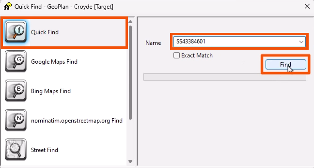
The model zooms to the node.
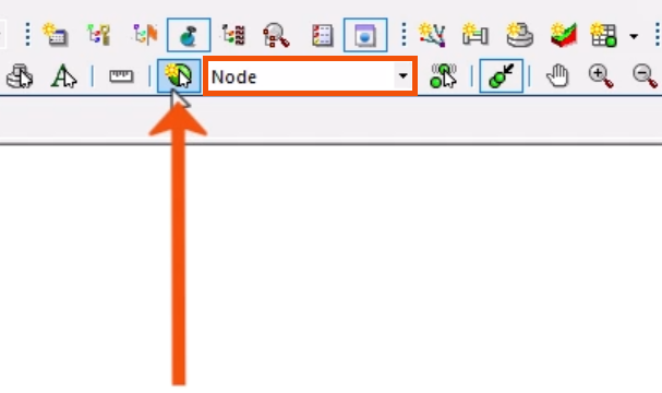
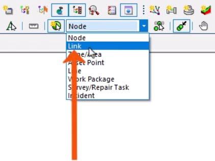
- From the GeoPlan Tools toolbar, expand the New Object Type drop-down and select Node.
- Click New Object.
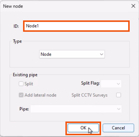
- On the GeoPlan, click to add a node near the found node.
- Name it “Node1”.
- Click OK.
- With the New Object mode still active, click nearby to add a second node.
- Name it “Node2”.
- Click OK.
Next, add pipes between the new nodes.
- Expand the New Object Type drop-down and select Link.
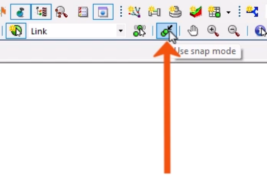
- From the toolbar, make sure that Use snap mode is toggled on.
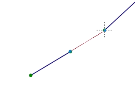
- Hover the cursor over Node2 until the cross appears, then click to start the link.
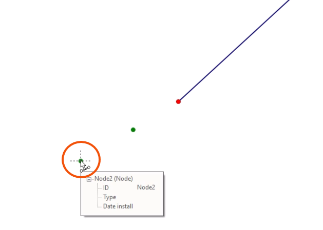
- Hover the cursor over Node1 until the cross appears, then click to close the link.
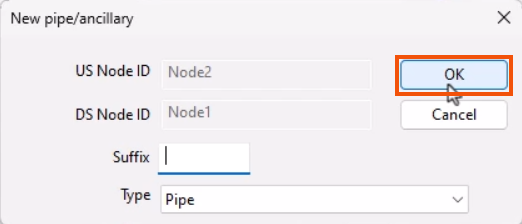
- In the New pipe dialog, click OK.
- Repeat these steps to link Node1 to the original node.
- Press ESC to toggle Link mode off.
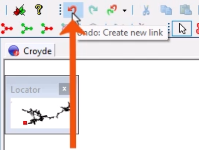
- If a mistake is made, from the Edit toolbar, click Undo.
Links should be created in the direction of the flow. To quickly change the flow direction of pipes:
- Select the two pipes that were just added.
- From the Selection toolbar, click Reverse all selected links.
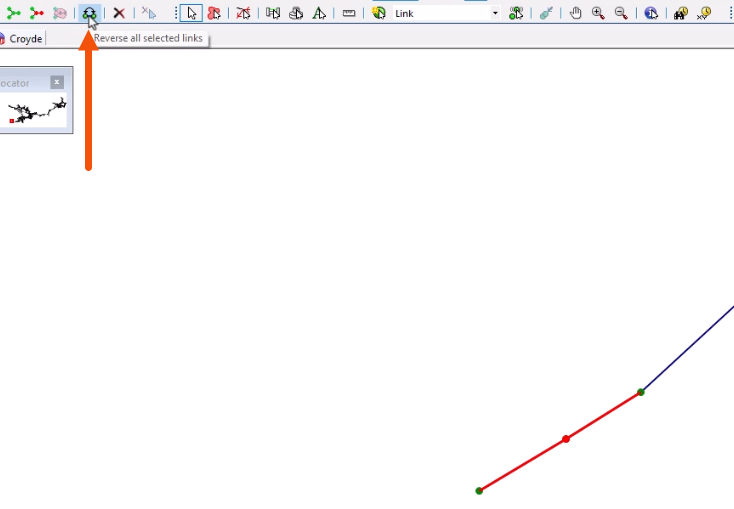
In this case, the upstream and downstream node IDs are reversed.
In this case, the two nodes were added with the placeholder names Node1 and Node2, but automatic naming can be set up, based on coordinates or a custom pattern.
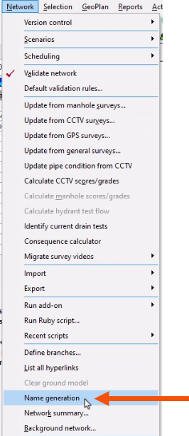
- In the GeoPlan, select the two nodes.
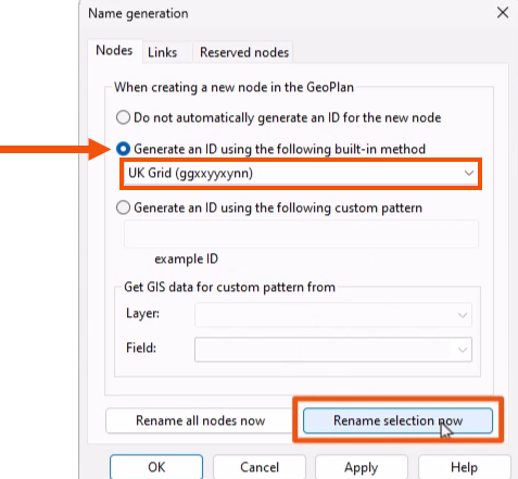
- From the Network menu, select Name generation.
- In the Name generation dialog, Nodes tab, select Generate an ID using the following built-in method.
- From the drop-down, select UK Grid to generate names based on the UK National Grid location.
- Click Rename selection now to update the two nodes.
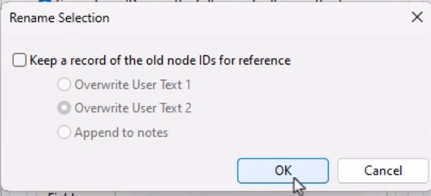
A popup provides the option to keep a record of the old node IDs for reference.
- Click OK to close the dialog.
A message confirms the nodes are successfully renamed. Any nodes added will now follow this naming pattern.