Re-digitizing newly connected pipes
Step-by-step guide
In a configured modeling project, once features have been added to the system, redrawing them can help to ensure that the pipe direction is correct.
In this model, pumps and a reservoir have just been added. The next step is to re-digitize the pipes, so they connect to the newly created pumps and reservoir. Keep in mind that because pipe direction dictates the direction that a pump operates, the pipes need to be drawn from the reservoir towards the system.
- On the InfoWater Pro ribbon, in the Edit panel, expand the Edit drop-down and select Redraw Pipe.
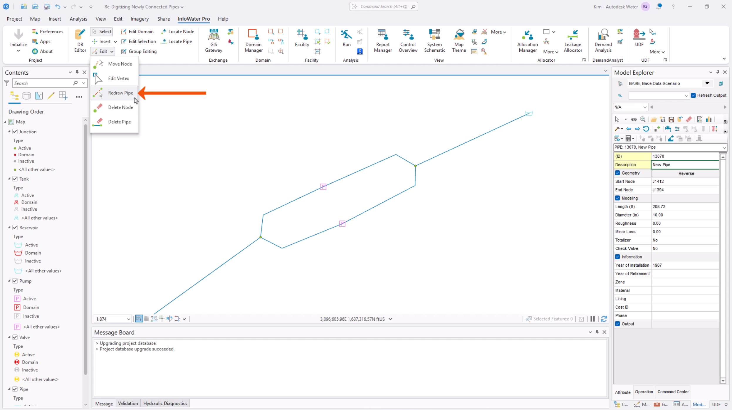
- Select a pipe to be redrawn.
This command redraws the currently selected pipe, so it is important to select the correct pipe. The selected pipe flashes to indicate that it will be redrawn.
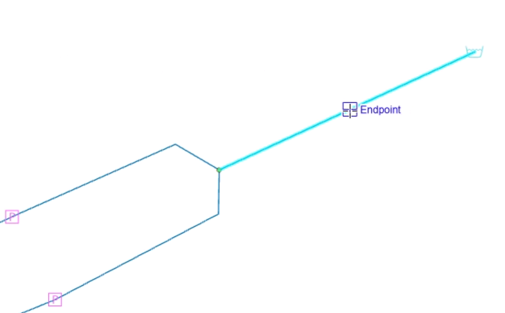
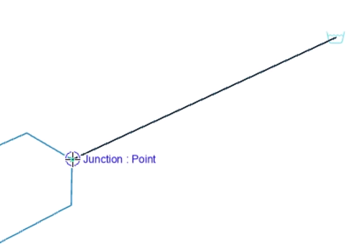
- Click a node to start the pipe.
Note that not clicking close enough to the start junction may inadvertently make another pipe flash. If this occurs, reselect the correct pipe, and when it flashes, repeat the selection of the start node.
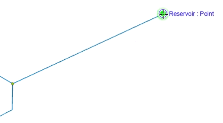
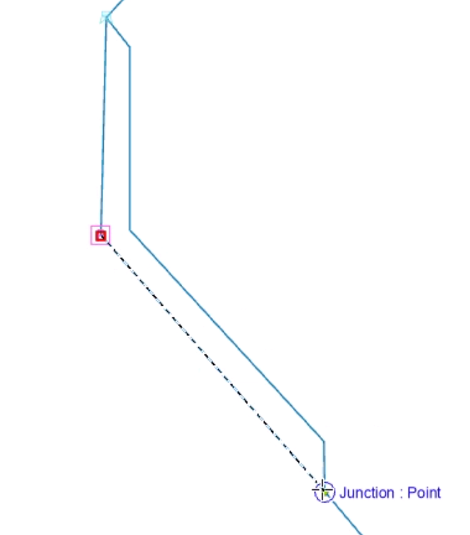
- Double-click a node to finish the pipe.
- Continue redrawing pipes.
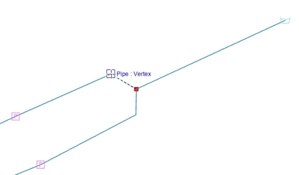
- Click to add intermediate vertices.
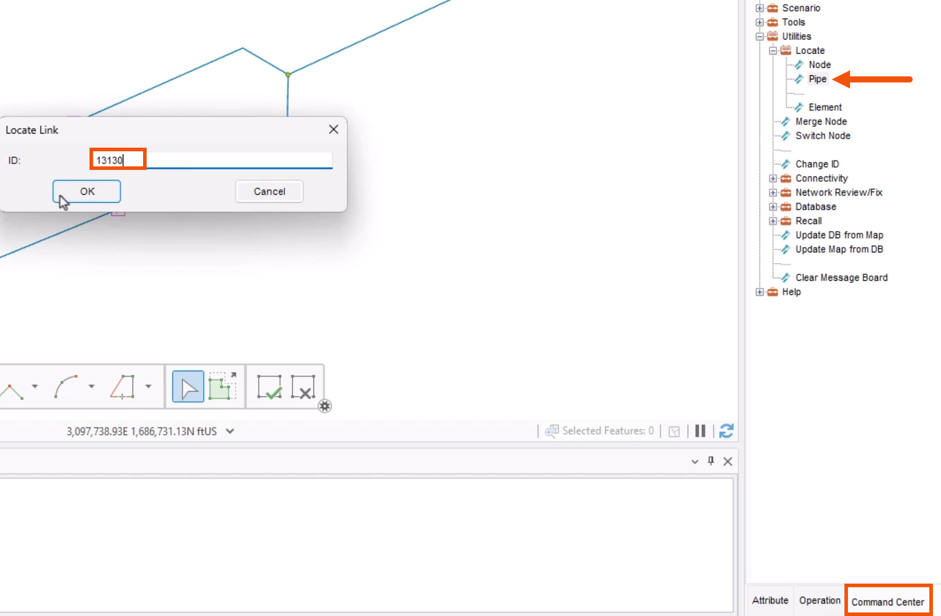
Repeat these steps to re-digitize two more locations—in this case, pipes 13130 and 12390.
For each location:
- In the Model Explorer, Command Center tab, select Utilities > Locate > Pipe.
- In the Locate Link popup, enter the pipe ID.
- Click OK.
- Again, redraw the corresponding pipes.
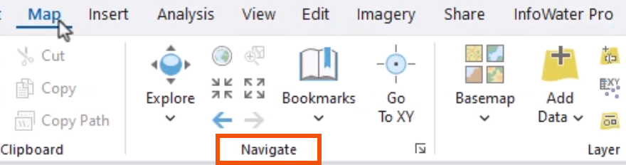
- On the ribbon, Map tab, Navigate panel, use the Zoom tools to center the model view as needed.
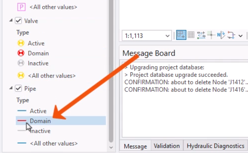
Next, edit the Domain pipe symbol to show the direction of each pipe.
- In the Contents pane, for the Pipe layer, double-click the red line for Domain pipes.
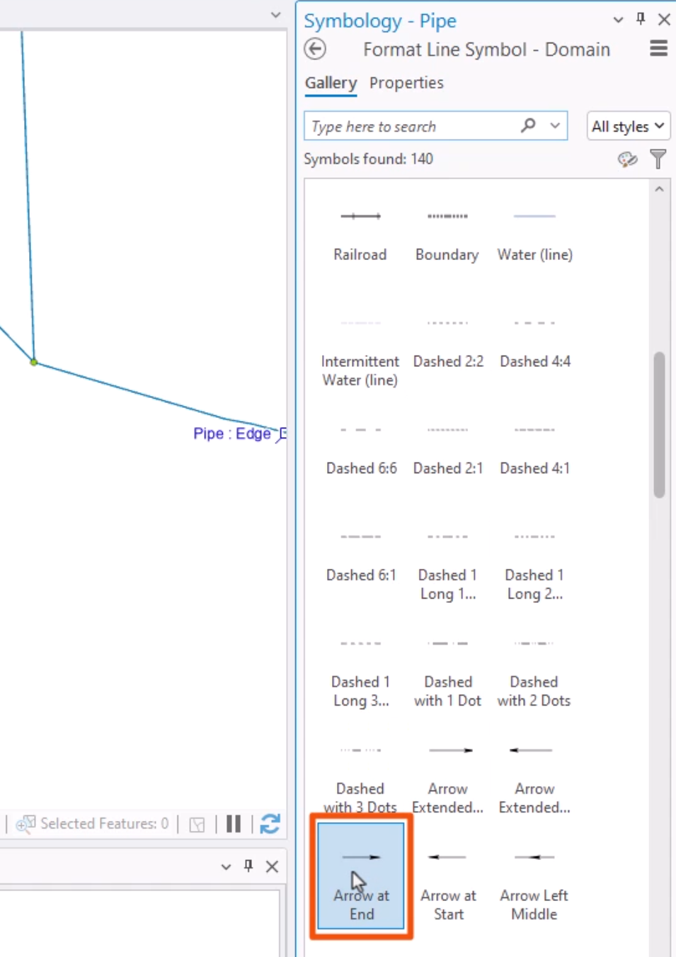
- Locate and select the Arrow at End symbol.
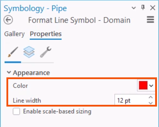
- Click the Properties tab.
- In the Color drop-down, choose a red similar to the Domain color.
- Increase the Line width—in this case, to 12 pt.
- Click Apply.
To view the direction of the pipes:
- On the ribbon, Domain panel, click Enlarge Domain.
- In the model, manually select all the pipes connected to pumps so that they are in the domain.
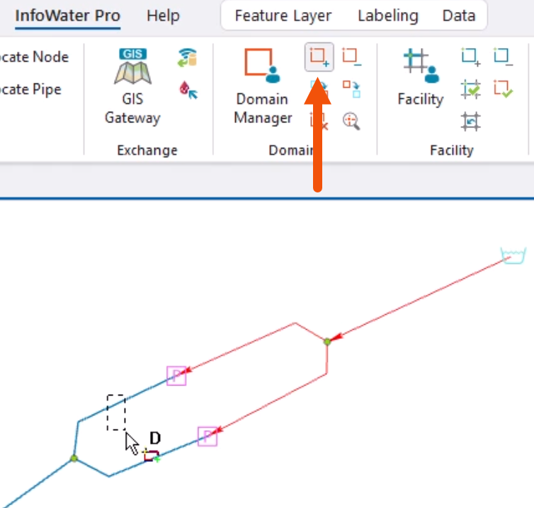
This will now show all pipes in the domain with an arrow at the end of the pipe to indicate its direction. Limiting this to the pipes in the domain avoids unnecessary clutter.
This feature is useful for quickly verifying the direction of key pipes in the system, especially pipes connected to pumps and valves, which must be drawn in the direction of water flow.
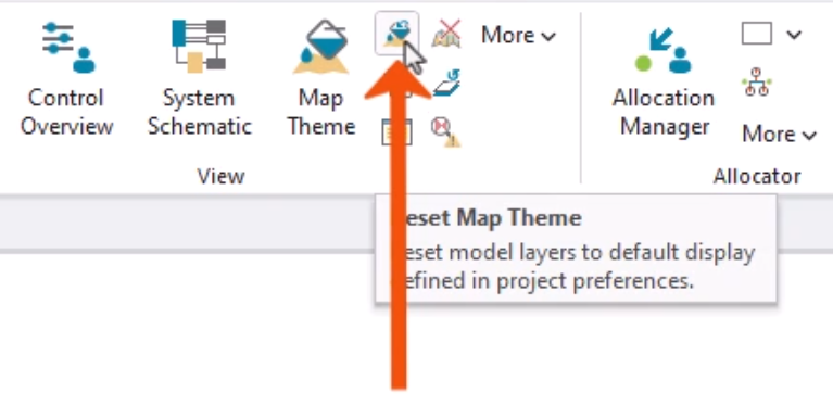
- To clear the domain pipes back to their default settings, on the InfoWater Pro ribbon, in the View panel, click Reset Map Theme.