Step-by-step guide
Reaeration boosts dissolved oxygen in rivers, and is crucial for water quality.
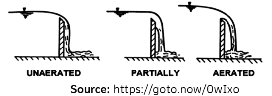
Hydraulic structures create white water and turbulence, promoting oxygen transfer.
In InfoWorks ICM, hydraulic structures (excluding pumps) are seen as control links for their effect on water quality and oxygen levels. For instance, a weir disrupts the water surface, promoting reaeration by increasing turbulence and oxygen diffusion.
In ICM, there are two options for defining reaeration coefficients:
- Uniform values set a global aeration coefficient for general structure reaeration calculations.
- Custom values can be used to override the global coefficient for individual structures, enabling a more tailored approach.
The reaeration coefficient depends on multiple factors, including structure type, head loss, temperature, flow, turbulence, and flow conditions.
For example, reaeration over a weir occurs through four processes:
- Water acceleration as water flows over a weir crest, increasing its velocity and generating turbulence.
- Surface diffusion, which enhances oxygen diffusion via the disrupted water surface.
- Plunging jet formation, where water plunges and mixes with air, enhancing oxygen transfer.
- Air entrainment, when tiny air bubbles are absorbed into the water column, boosting DO levels.
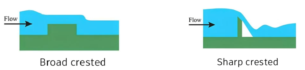
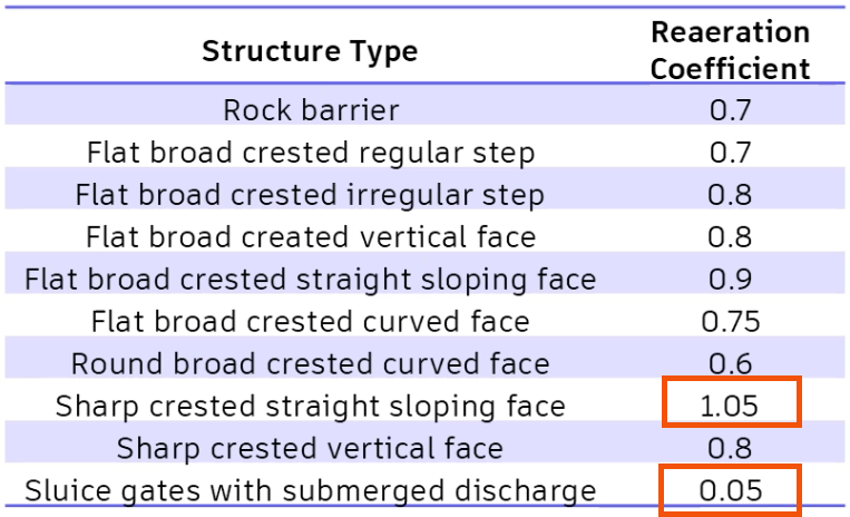
The reaeration coefficient also varies by structure type. Sluice gates with submerged discharge have low reaeration coefficients, as they limit air-water interaction, whereas sharp crested weirs with a sloping face have higher coefficients, promoting efficient oxygen transfer.
Different structure types can be assigned specific reaeration parameters in ICM to help ensure accurate modeling of dissolved oxygen dynamics.
Structures such as sharp crested weirs with a straight sloping face have the highest reaeration coefficient at 1.05, due to significant turbulence and air entrainment. Conversely, sluice gates with submerged discharge have minimal reaeration with a coefficient of 0.05.
Next, create two different scenarios: one where the reaeration coefficient is defined with a uniform value, and one where the coefficient is defined with a custom value for a specific structure—in this case, an irregular weir. Then, compare the two scenarios, which have the same constant flows, to analyze the effect of reaeration on dissolved oxygen levels.
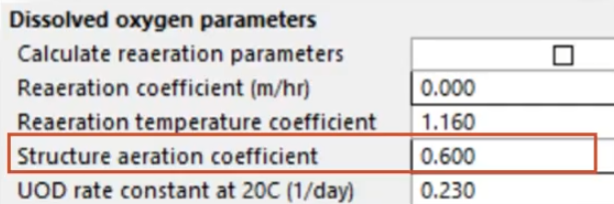
To define the reaeration parameters for the general, or uniform, value:
- In the GeoPlan, select the irregular weir.
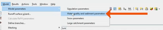
- Navigate to Model > Model parameters > Water quality and sediment parameters.
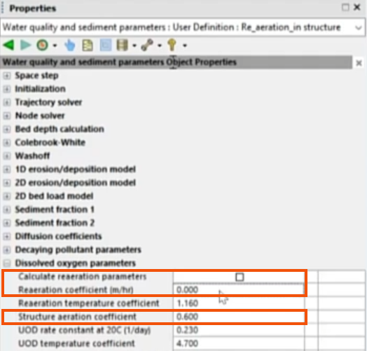
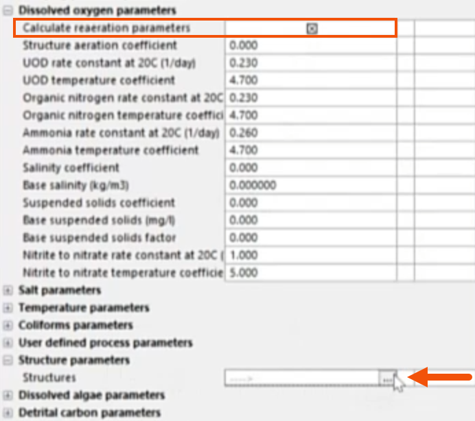
- Under Dissolved oxygen parameters, set the Structure aeration coefficient to 0.6.
- Confirm that Calculate reaeration parameters is deselected, so that the reaeration parameters will be used.
- Set the Reaeration coefficient to 0 meters per hour, so that no additional oxygen transfer occurs, other than at the structure.
- Validate and commit the scenario.
- Open the Run dialog for the scenario to set the run details. In this case, it has already been configured.
- Click QM parameters.
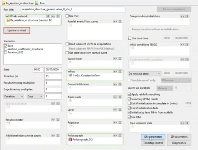
- In the QM Parameters dialog, select the appropriate parameters. To help ensure consistency, it is best practice to use the same QM parameters specified in previous water quality saturated DO simulations.
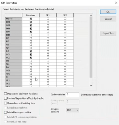
- Click OK.
- In the Run dialog, click Run simulations.
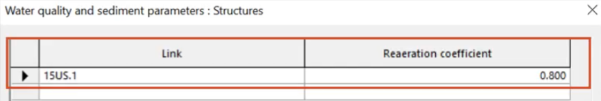
Now, create the second scenario with a reaeration coefficient that is customized to the irregular weir.
Remember that reaeration rates are impacted by reaeration coefficients and by the different hydraulic structures.
- Navigate to the Water quality and sediment parameters.
- Under Dissolved oxygen parameters, enable Calculate reaeration parameters.
- Expand Structure parameters.
- In the Structures field, click More (…).
- In the Structures dialog, assign a Reaeration coefficient of 0.8 to the irregular weir.
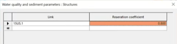
- Click OK.
- Validate and commit the scenario.
- Again, open the Run dialog for the scenario to verify the run details and the QM parameters.
- Run the simulation.
Compare the results of the two runs, with and without structure-specific reaeration coefficients, to analyze the changes in the dissolved oxygen concentration.
- With the irregular weir selected, navigate to Results > Graph reports > Simulation report.
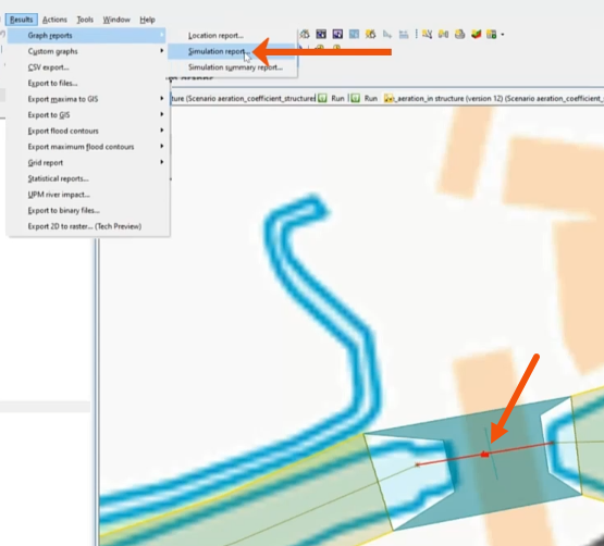
- Drag the two scenarios from the Explorer window into the Simulations dialog.
- Set the Selection List to the irregular weir, or Current selection.
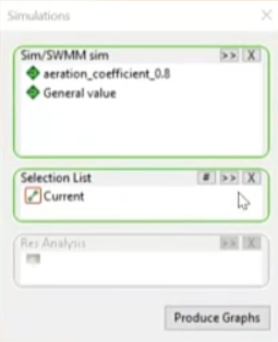
- Click Produce Graphs.
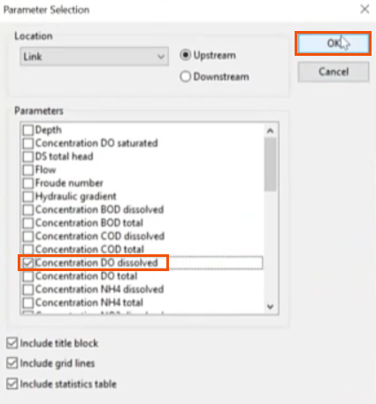
- In the Parameter Selection dialog, select Concentration DO dissolved.
- Click OK.
- Review the resulting plots.
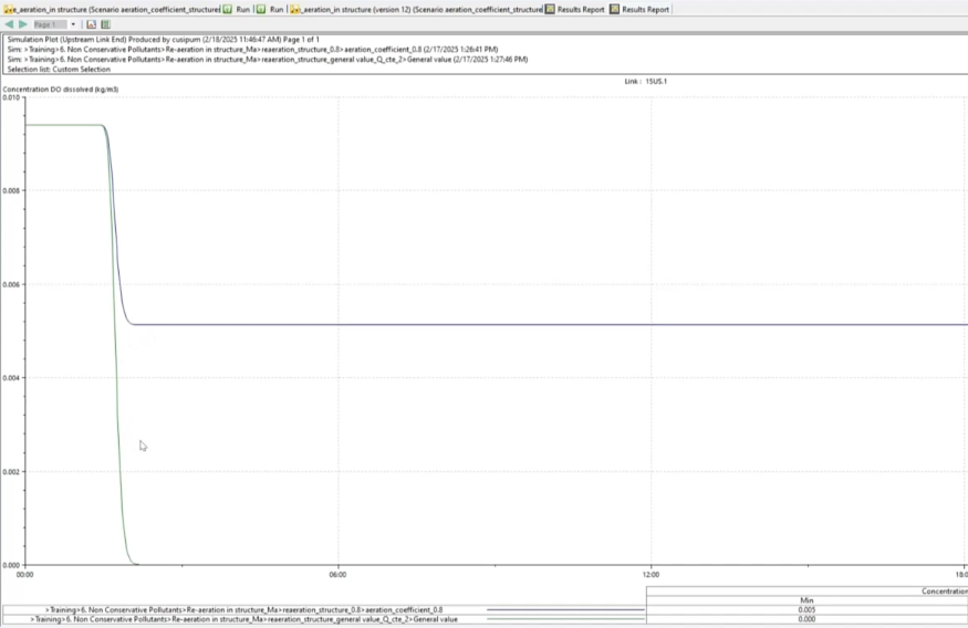
When the reaeration coefficient is set as a global value for the structure, the dissolved oxygen concentration drops to zero.
When the value for each hydraulic structure is set individually, the concentration does not drop to zero, and a constant value is maintained.


