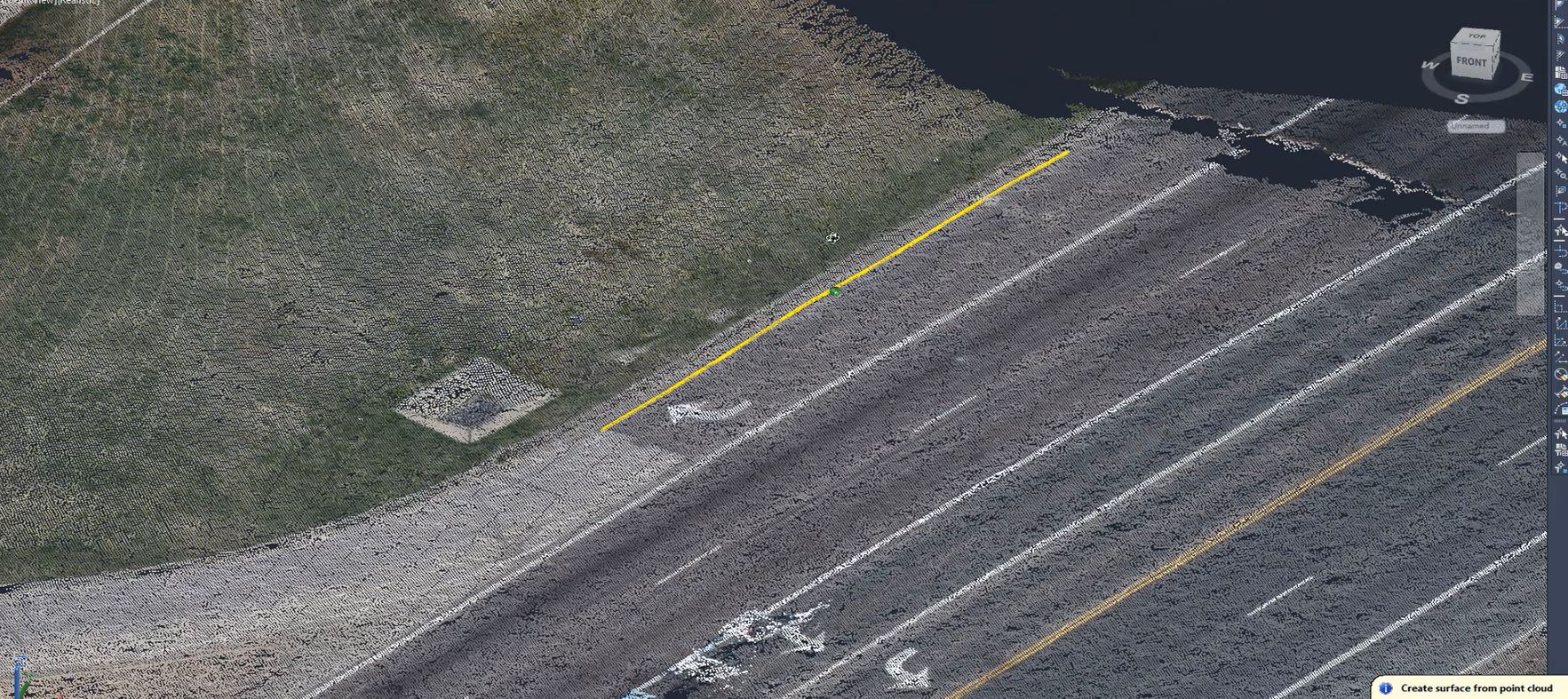
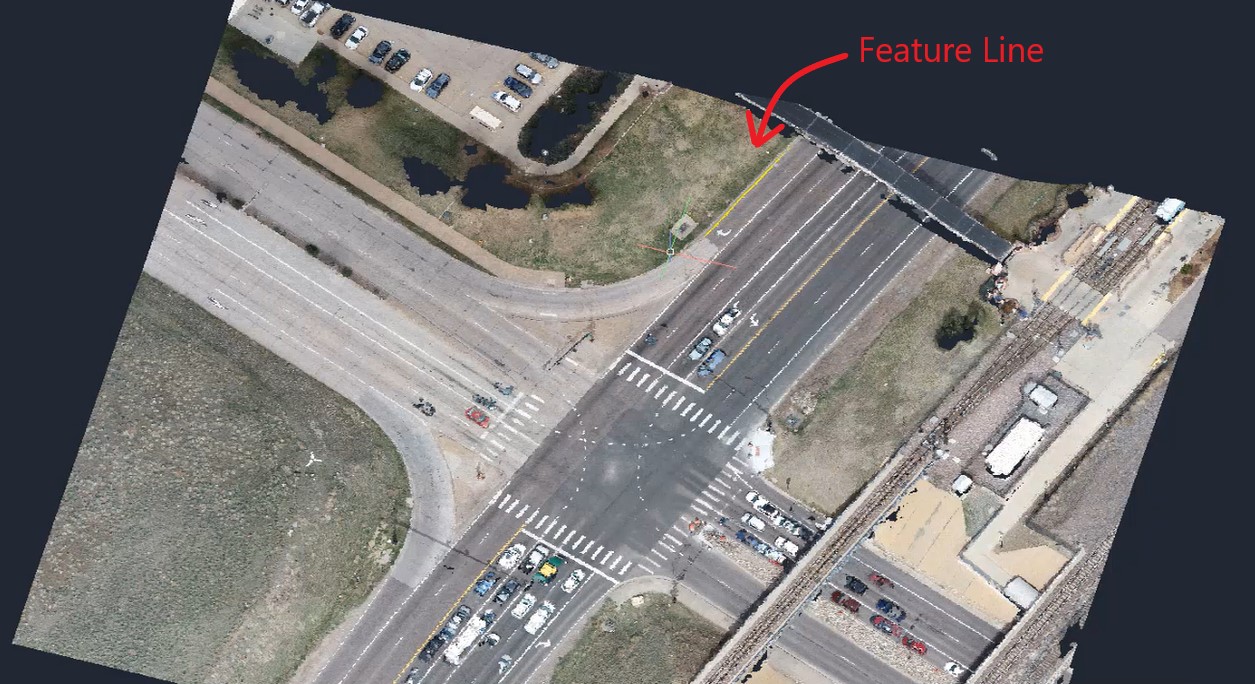
In this session, we’re going to review bringing point cloud into Civil 3D and utilizing it to create things like surfaces, breaklines and points. There are a few methods to do this:
Create a TIN surface from points within RCS format point cloud scan files and RCP format point cloud project files created with Autodesk ReCap.
o Create a surface from several point clouds.
o Create a surface from defined/selected area
o Filter non-ground points
Create 2D & 3D Geometry from point clouds.
o Use automagte3d feature extraction tool
o Draw/create COGO points
o Draw/create feature lines or 3D polylines
Task: Convert Point Clouds into Geometry
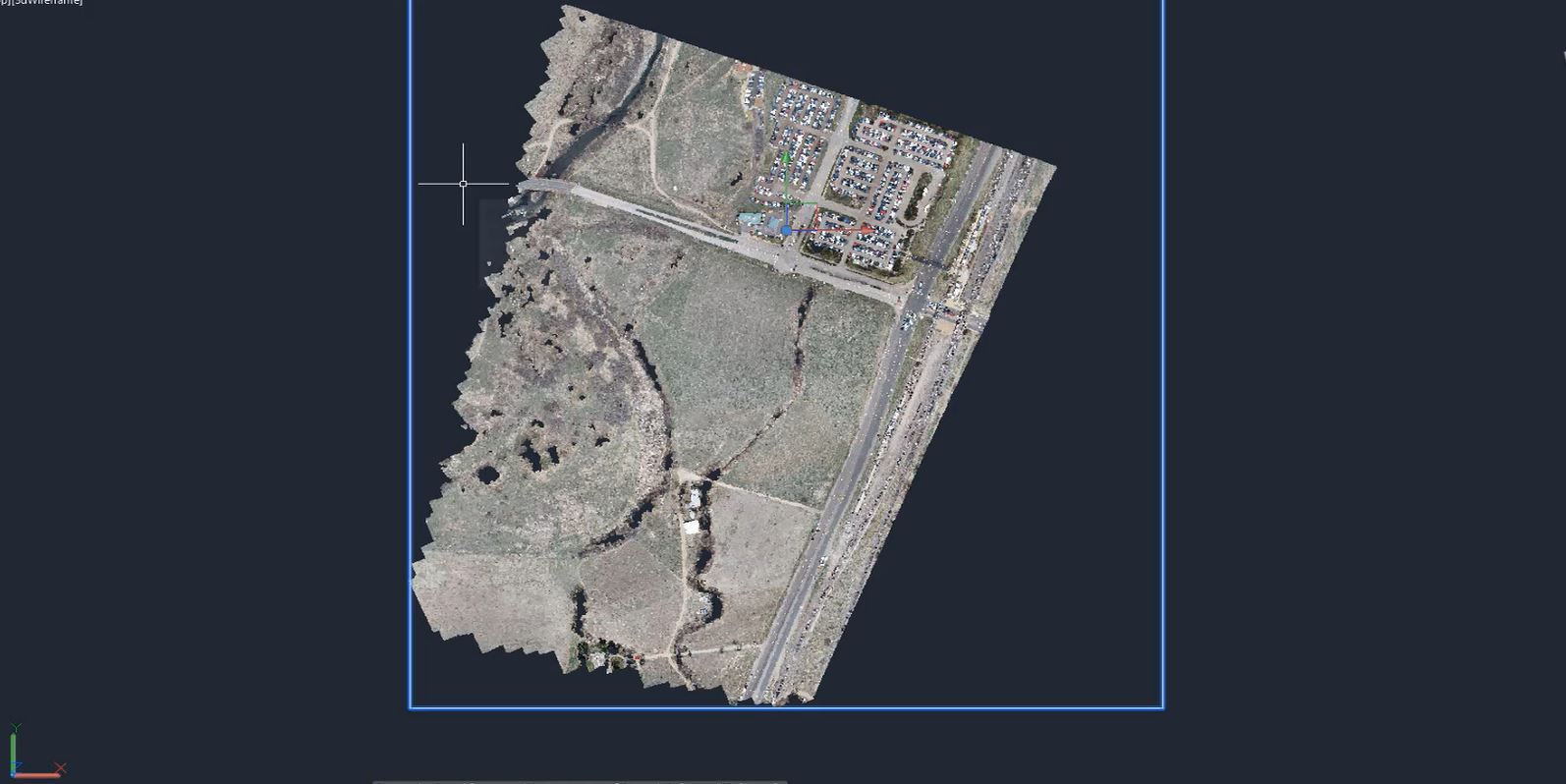
- We begin with a point cloud in Civil 3D. We want to create a surface from this point cloud, so select the point cloud.
- If your point cloud is classified, you can turn the “Classification” tool on and off to check it out.
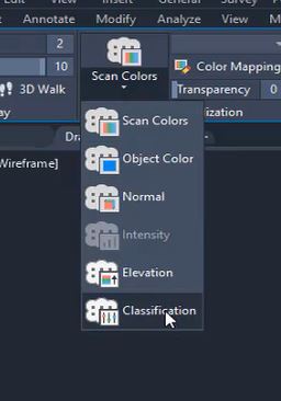
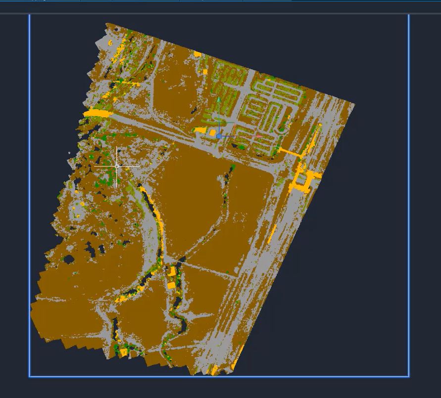
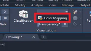
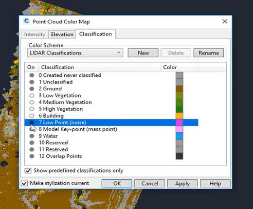
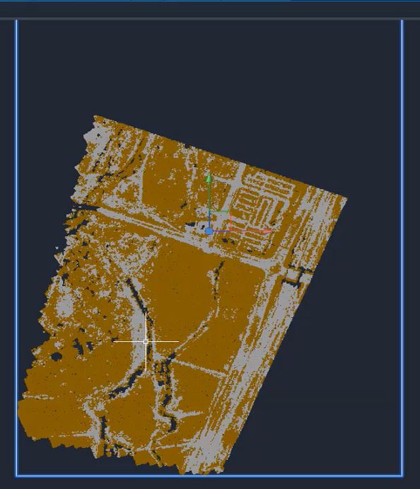
- Use the “Color Mapping” option to edit the classifications to make creating your surface more specific.
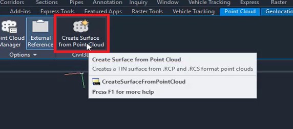
- With the point cloud selected, select “Create Surface from Point Cloud” from the “Civil 3D” panel at the top of the screen.
- window titled “Create TIN Surface from Point Cloud – General” will appear. Name the surface and select a style. For this example, we are using the “Contours 1’ and 5’ (Background)” style.
- Select “Next”.
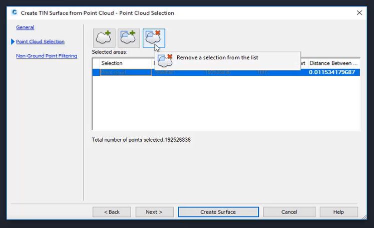
- We can create a surface from our entire point cloud or multiple point clouds, but the point cloud in our example has millions of points. So, we’re going to define a new area by selecting the point cloud in the list and clicking “Remove a selection from the list”.
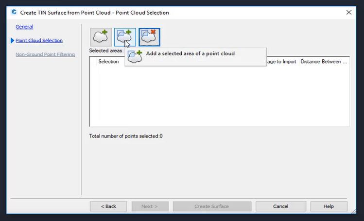
- Then select “Add a selected area of a point cloud” and window a polygon-shaped area.
- The “Create TIN Surface from Point Cloud’ window will appear again and show you the number of points selected. Although we have less points now, we still have more than we want to take into Civil 3D, so we’re going to do some filtering.
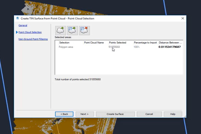
- First, change the distance between points to about “5”. You’ll notice immediately that the number of points will do down.
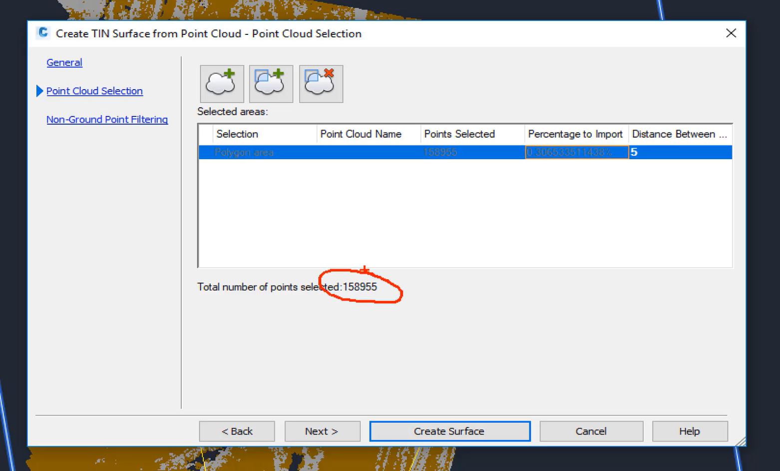
- Select “Next” and choose a filter. The box on the right will give you a display of what may happen on your surface. For our example, we will select “No filter” because we already have a classified point cloud that we’ve removed the vegetation and some of the buildings from.
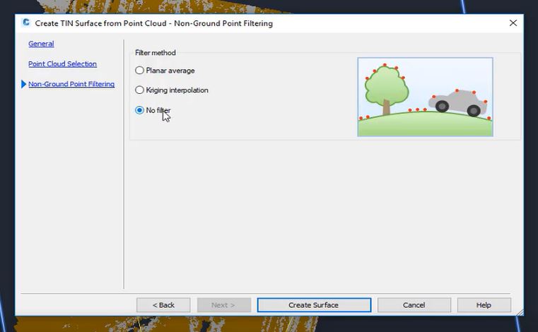
- Click “Create Surface” and then select “Close” in the processing window. While that processes, we can continue to work.
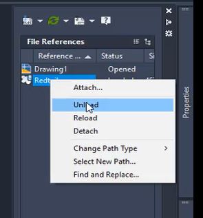
- Next, we want to just see the surface, so unload the point cloud by selecting “External References” from the right side of the screen and right-clicking on “Redtail” and selecting “Unload”.
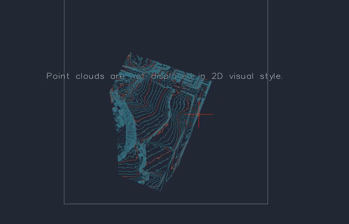
- Select the surface and view is as a “Top” view with a “2D Wireframe” and do a zoom extense.
- To draw a feature line in your surface, reload the point cloud, turn the surface to a “No Display” style and return the colors of the surface to “Scan Colors”.
- Next, crop out a section of the point cloud. In our example, we’ll focus on an intersection.
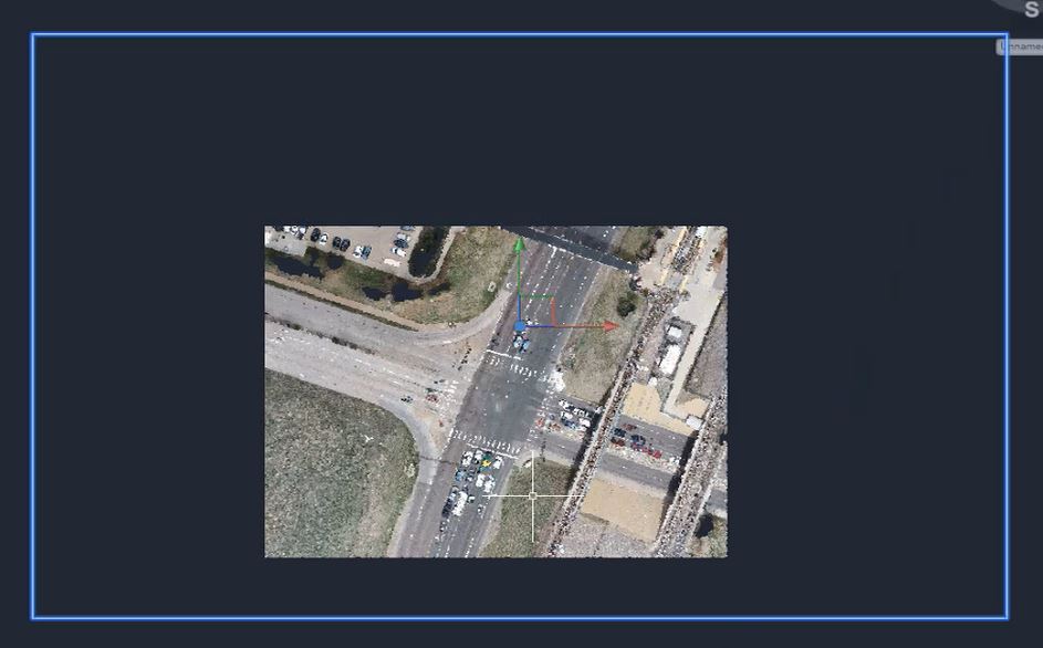
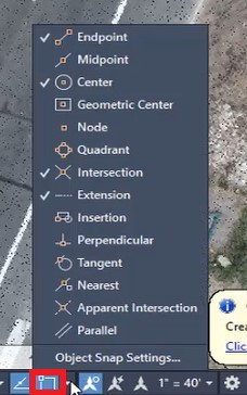
- From here, you can add a feature line, a 2D polyine or a 3D polyine. In this example, we’re going to add a feature line to an edge of pavement. First, make sure the 3D snap is on by selecting the “Object Snap Settings” at the bottom of the screen.
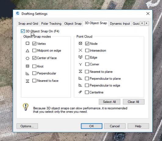
- In the window that appears, select the “3D Object Snap” tab and check the box for “3D Object Snap On”. And select “Node” from the “Point Cloud” list and hit “OK”.
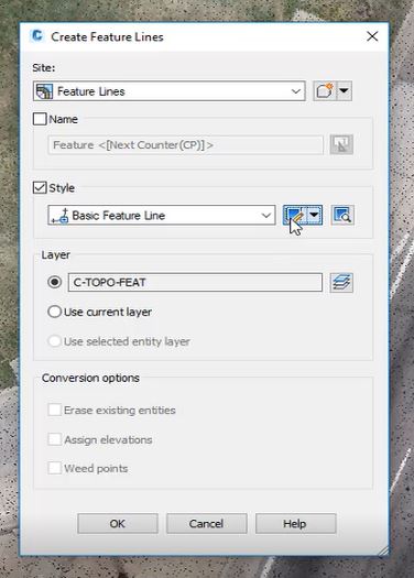
- Then go to the “Home” tab and select “Feature Line” from the ribbon and then “Create Feature Line”.
- In the “Create Feature Lines” window that appears, select “Feature Lines” as the “Site” and “Basic Feature Line” as the “Style”.
- We’re also going to edit the style further by clicking on the edit button next to the “Style” drop-down menu.
- In the window that appears, select the “Display” tab and choose “Model” in the “View Direction” drop-down menu. Change the color and lineweight to something more visible. For our example, we’re choosing the color yellow and a lineweight of “0.50 mm”.
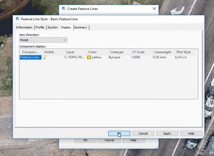
- Select “OK”.
- In the feature line command, you’ll see a blue “x” within a circle where your cursor is going. This blue marker shows up when it’s snapping to a node in the point cloud.
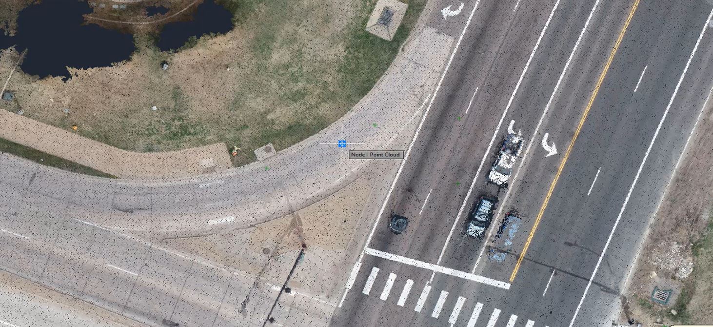
- Now we’ll find an edge of pavement and click on the point where we want to start. The command bar will ask to specify the elevation, just hit “Enter”. Continue this click-and-enter process to build your line.
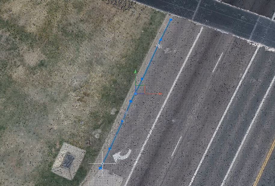
- Now, you can see this feature line draped on the opint cloud and add them to a surface as well as extract objects like paint lines and curbs and gutters.
