• Revit

Introduction to mechanical settings for duct and pipe standards

Access and review the key settings and options for duct and pipe standards.


Step-by-step guide

Access and review the key settings and options for duct and pipe standards.
  1. Start a new project using the template Mechanical – Default.rte.
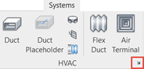
  2. On the Systems tab, HVAC panel, click the Mechanical Settings dialog launcher.On the Systems tab, HVAC panel, the dialog launcher is highlighted in red.
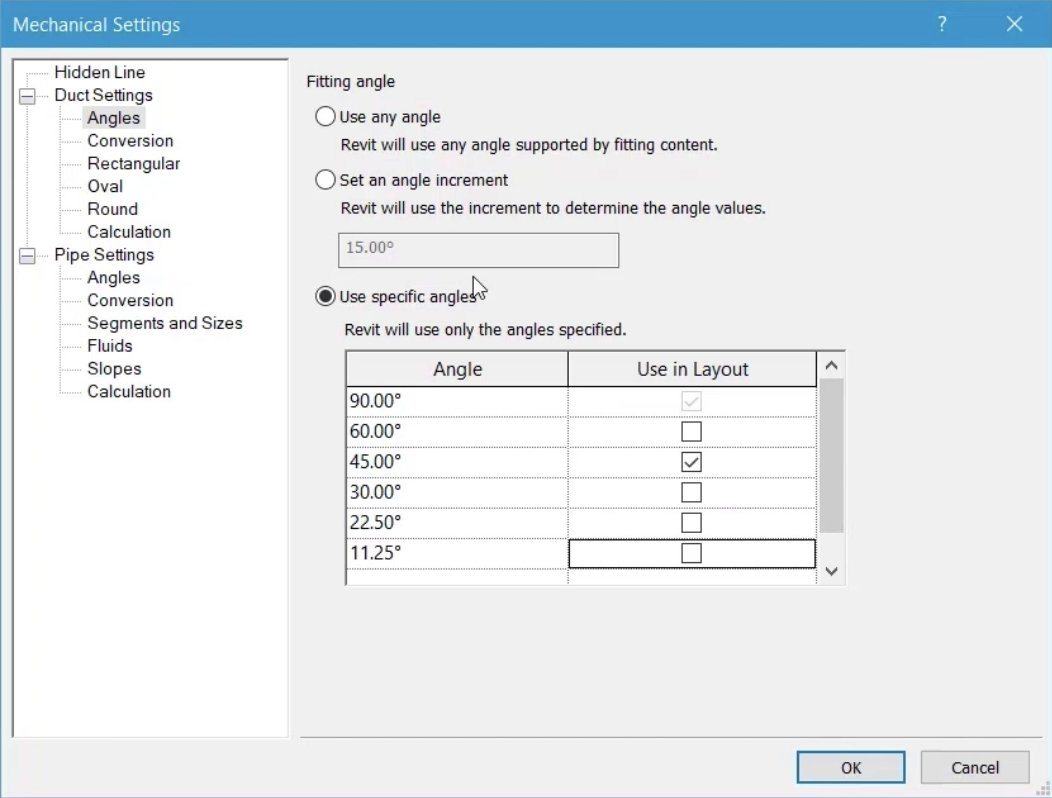
  3. Under Duct Settings, select Angles.
  4. Select Use specific angles.
  5. In the list of angles, deselect all options except 45°.
    In the Mechanical Settings dialog box, Angles is selected in the left panel, and all settings are configured for this example.
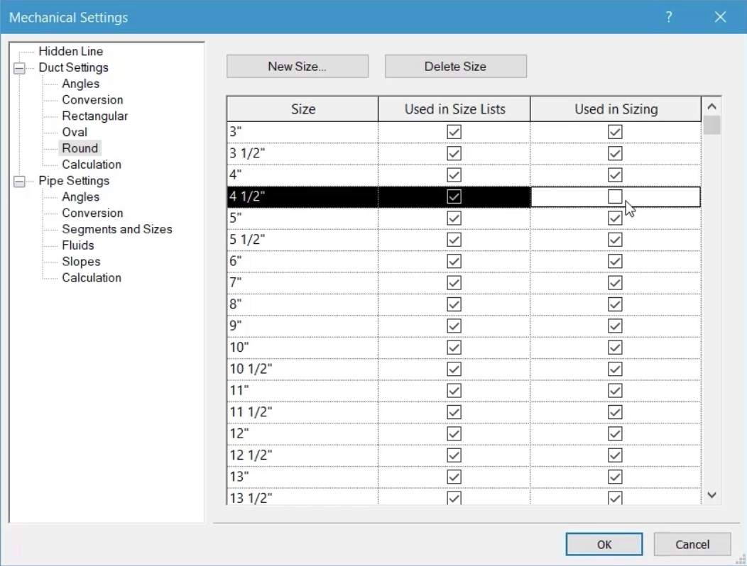
  6. Review the size range and options for Rectangular, Oval, and Round ducts.
  7. From the list of available Round sizes, for 4 1/2", deselect Used in Sizing.In the Mechanical Settings dialog box, Round is selected, and the Used in Sizing option is deselected for the 4 ½ in. size.

This allows the user to select this size, but prevents it from being selected when using the duct sizing tools.
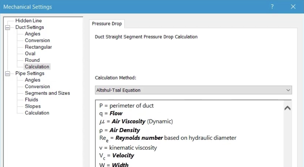
  1. Select Calculation and review the options for calculating the pressure drop in a straight segment of duct. Also, note the Revit parameters shown in bold that are used as part of each calculation.In the Mechanical Settings dialog box, Calculation is selected to display the options for calculating the pressure drop in a straight segment of duct.
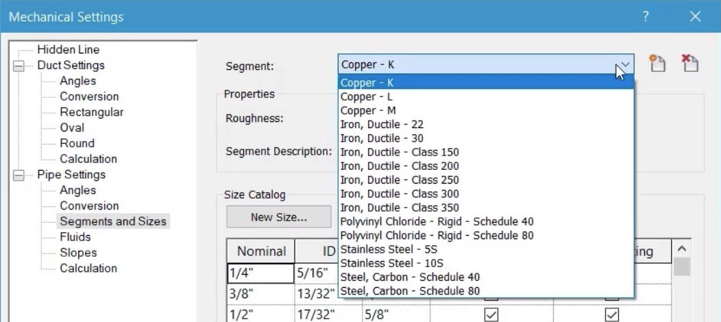
  2. Under Pipe Settings, select Segments and Sizes to review the available segments.In the Mechanical Settings dialog box, Segments and Sizes is selected, and the Segment list is expanded to show the available options.
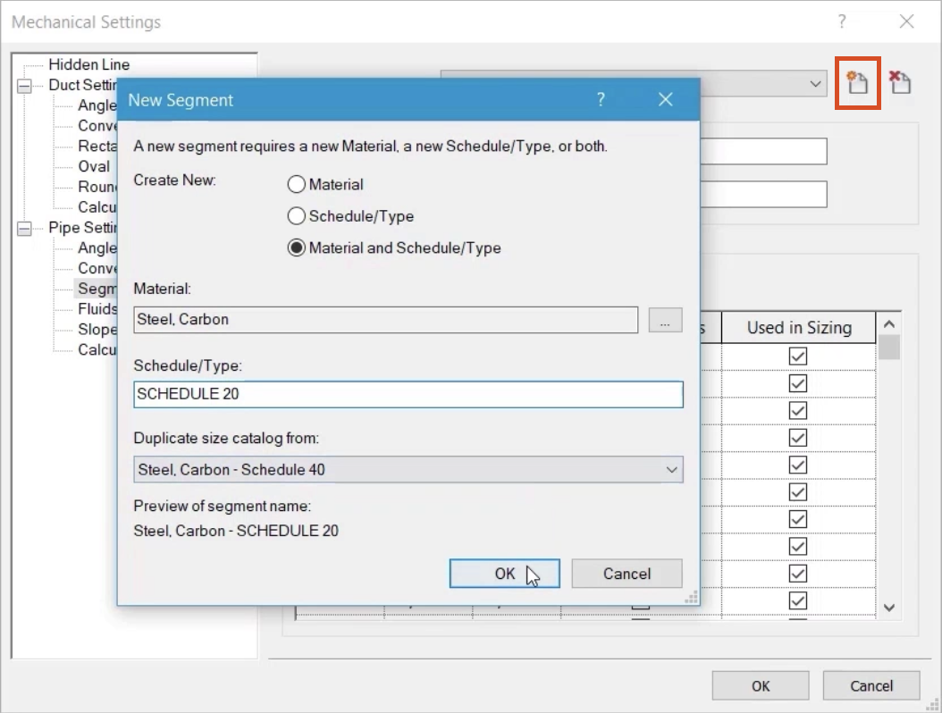
  3. Click Create New Pipe Segment.
  4. In the New Segment dialog box, select Material and Schedule/Type.
  5. Set the Material to Steel, Carbon.
  6. In the Schedule/Type field, enter "Schedule 20".
  7. Under Duplicate the size catalog from, select Steel, Carbon – Schedule 40.
  8. Click OK.
    In the Mechanical Settings dialog box, Create New Pipe Segment is highlighted in red, and in the New Segment dialog box, settings are configured for this example.
  9. Add and remove sizes from the size catalog as required for the Schedule 20 segment.From the Mechanical Settings dialog box, in the Segments and Sizes settings, a zoomed-in view of the Size Catalog group box.
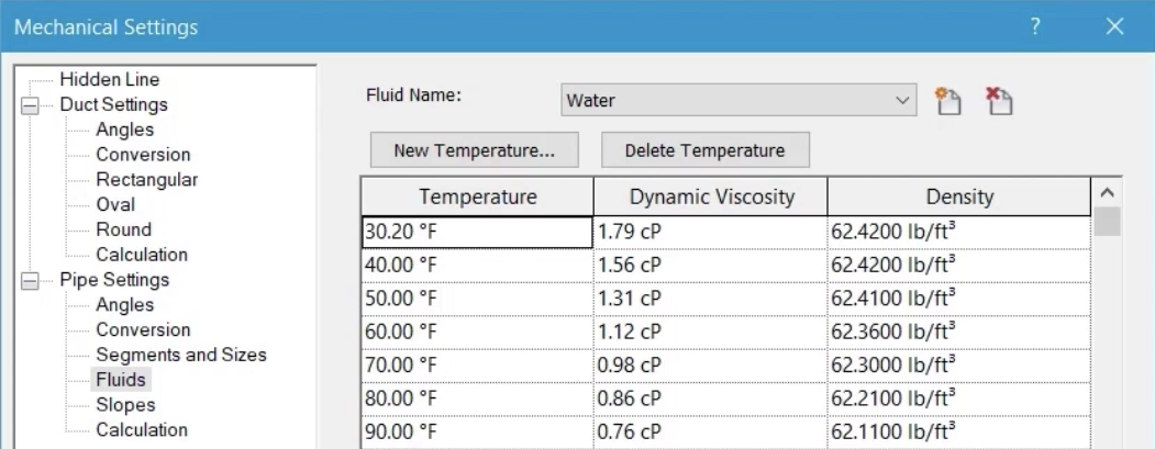
  10. Under Pipe Settings, select Fluids to review the available options.

Fluids are applied to piping systems, and their properties will have a bearing on the outcome of any pipe sizing that is carried out.
  1. Click OK.
    In the Mechanical Settings dialog box, Fluids is selected to display the available options.
  2. Draw a short section of pipe.
  3. Highlight and select the piping system.
    In the view, a short section of pipe is drawn and selected.
  4. In Properties, click Edit Type.
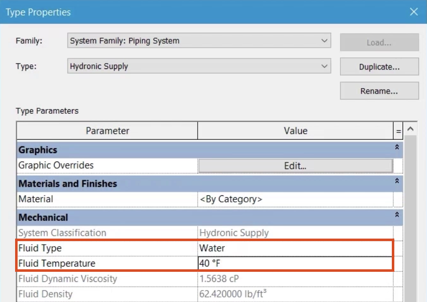
  5. In the Type Properties dialog box, review the options to change the fluid type and fluid temperature.
  6. Click OK.
    In the Type Properties dialog box, the Fluid Type and Fluid Temperature options are highlighted in red.
  7. In the Mechanical Settings, under Pipe Settings, select Slopes.
  8. Click New Slope.
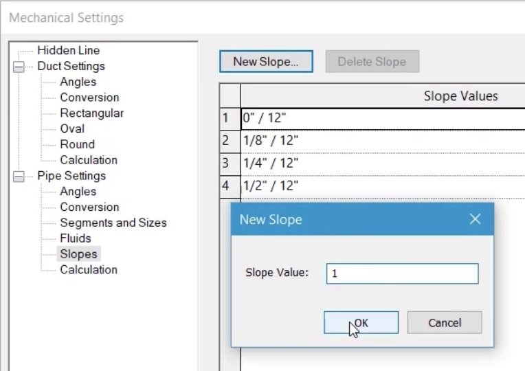
  9. In the New Slope popup, enter a value of 1.
  10. Click OK to create a new slope of 1" / 12".
    In the Mechanical Settings dialog box, Slopes is selected, and in the New Slope popup, a Slope Value of 1 is entered and OK is being selected.
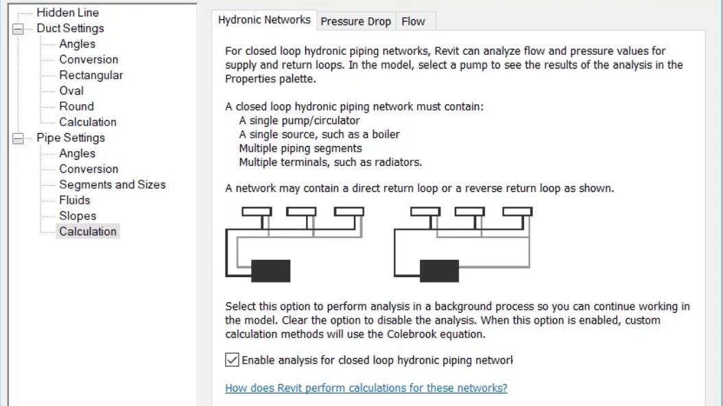
  11. Under Pipe Settings, select Calculation and review the information on the Hydronic Networks tab.In the Mechanical Settings dialog box, Calculation is selected under Pipe Settings, with the information on the Hydronics Networks tab displayed.
  12. Select the Pressure Drop tab and review the options for calculating the pressure drop in a straight segment of pipe.
  13. Select the Flow tab and review the information relating to calculation for those piping systems using Fixture Units, such as domestic hot and domestic cold.
  14. Click OK to close the Mechanical Settings dialog box.