Select network objects in InfoAsset Manager
Step-by-step guide
When a network is opened, a map-based display, or GeoPlan, shows a geographical representation of the network. It can be displayed over the top of a map or other background data.
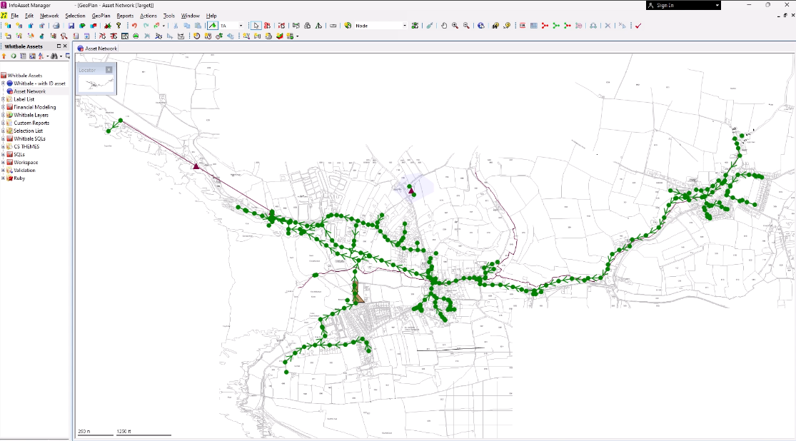
In this example, the entire network is visible, but when only a specific area is displayed, the GeoPlan Locator Map pinpoints your location within the network.
- Zoom in anywhere in the network.
Now, the locator map now includes a highlighted box to represent the current location. This box can be dragged to move the area displayed in the GeoPlan window.
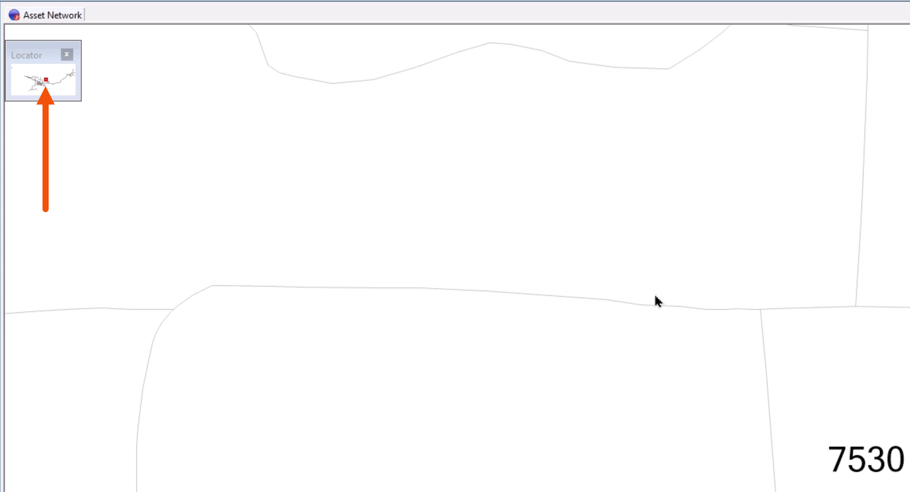
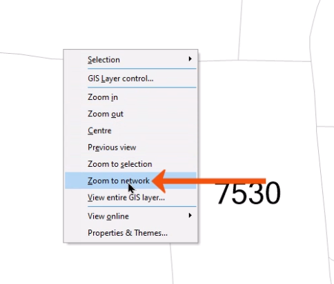
- To display the entire network again, right-click the GeoPlan and select Zoom to network, or press F12.
Several tools and keyboard shortcuts enable the selection of network objects on the GeoPlan. The simplest way to select objects is to use the Selection tool.
- From the GeoPlan Tools toolbar, click Select.
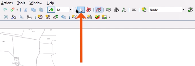
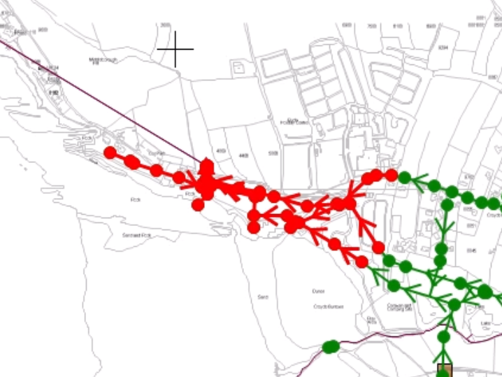
- In the GeoPlan, click an object. The selected object is now displayed in red.
- To add more objects to the selection, press and hold CTRL while clicking each additional object.
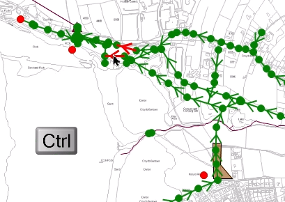
- To remove an object from the selection, while still holding CTRL, click the object a second time.
To select all objects in a specific area:
- Click and drag a rectangular window to select all objects within the rectangle.
For greater flexibility, draw a polygon to select objects in a defined area.
- On the GeoPlan Tools toolbar, click the Polygon Select tool.
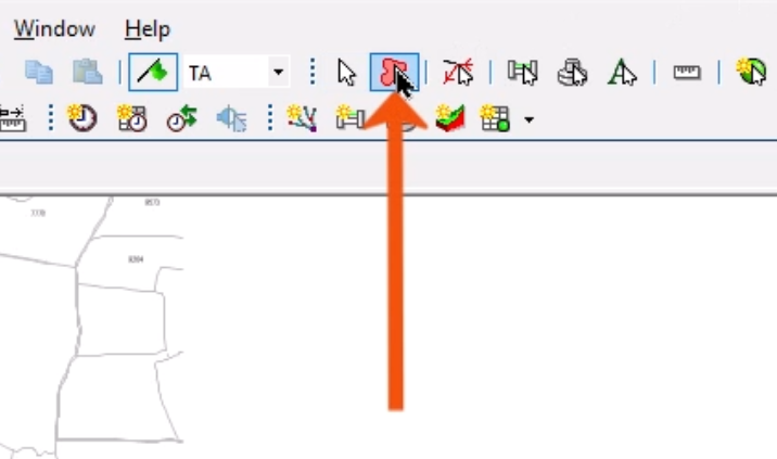
The cursor changes to a cross.
- Click in the GeoPlan to start creating the selection area, noting that the cursor is now connected to that point with a red line.
- Continue to click a series of points to draw a polygon around the selection region.
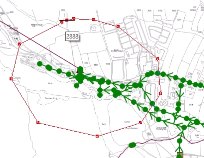
- Double-click at the last point to link to the starting point and close the polygon.
A network object is selected if its center point falls within this region.
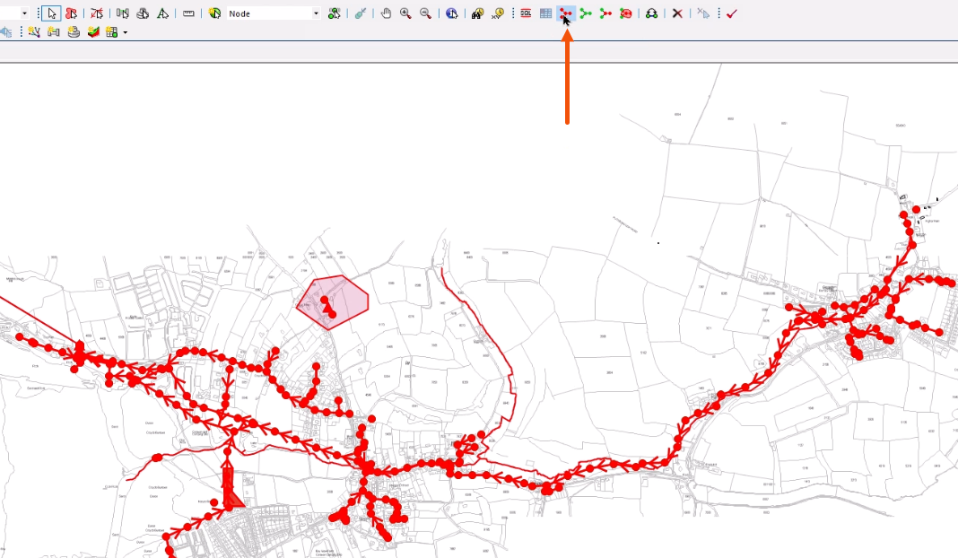
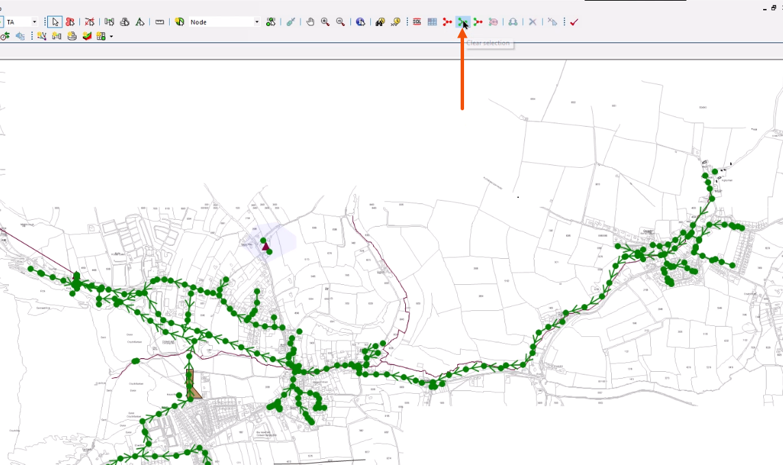
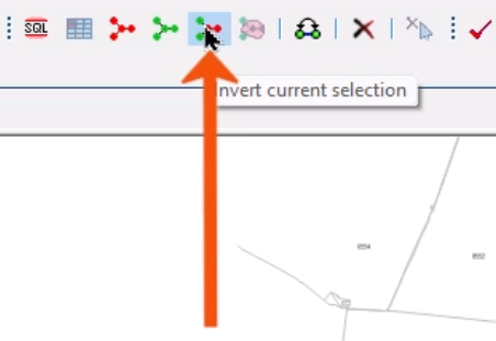
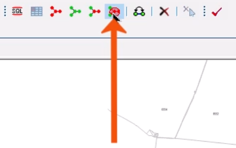
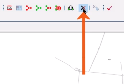
The Selection toolbar includes several commands to help select and deselect objects.
- Click Select all objects to select all objects in the network.
- Click Clear Selection to deselect any selected objects.
- Click Invert current selection to select the currently unselected objects and deselect the currently selected objects.
- Click Select all objects in polygons to select objects contained within the currently selected polygons.
- To delete a selected object, click Delete selection.
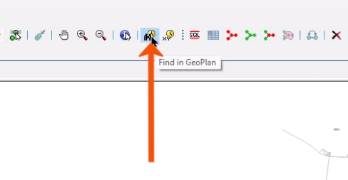
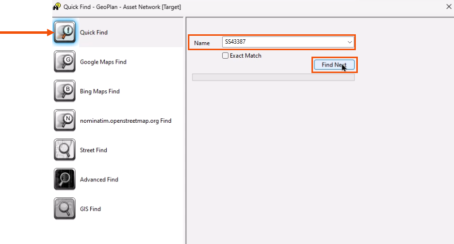
Objects can also be selected based on search results.
- From the GeoPlan Tools toolbar, click Find in GeoPlan to open the GeoPlan Find dialog.
- With Quick Find selected, in the Name field, enter the object to search for.
- Click Find or Find Next to pan to and select the next search result in the GeoPlan.
- Switch to Advanced Find and repeat the same search.
This time, all objects with IDs that include the string are listed.
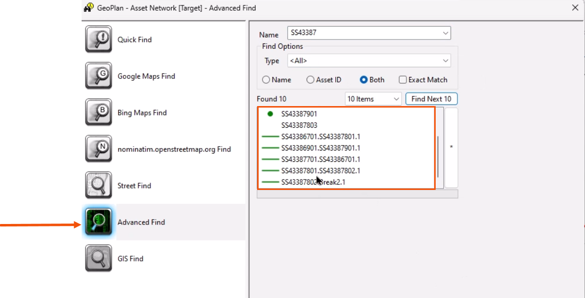
- Select an object in the results to find it in the GeoPlan.
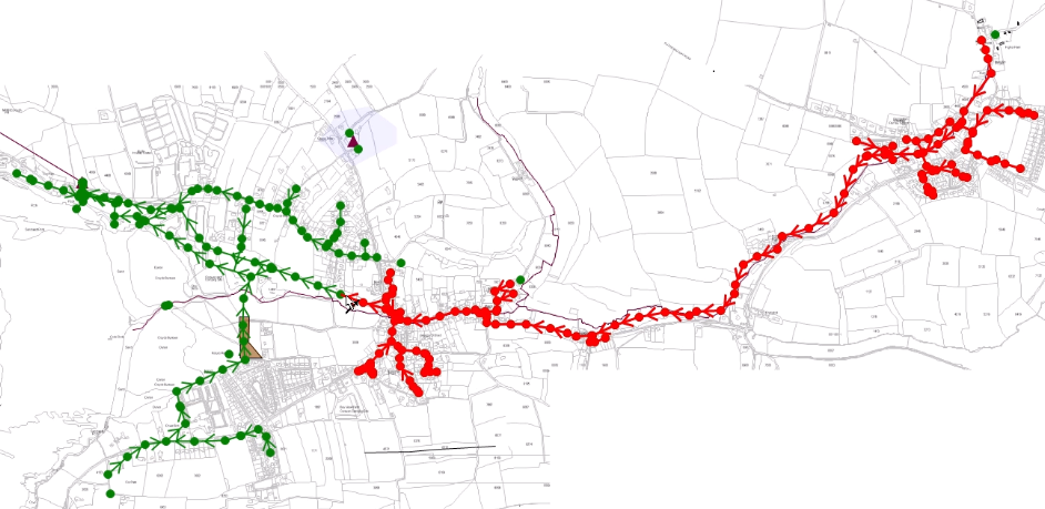
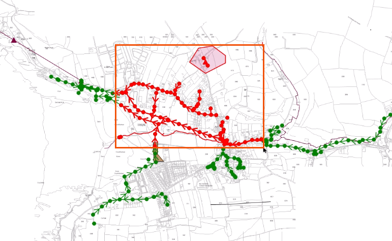
To trace paths from a starting point:
- From the toolbar, click Trace and select links upstream or Trace and select links downstream.
- Click a node or pipe in the GeoPlan.
In this case, the upstream tool was selected, so the tool selects all possible upstream paths from the starting point.