Use the Long Section window in InfoAsset Manager
Step-by-step guide
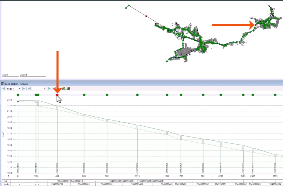
In InfoAsset Manager, Long Sections are useful for inspecting runs of nodes and pipes. The Long Section window displays a cross-section of network objects through the length of a selected run.
To open the Long Section window:
- From the GeoPlan Tools Toolbar, click Long Section pick.
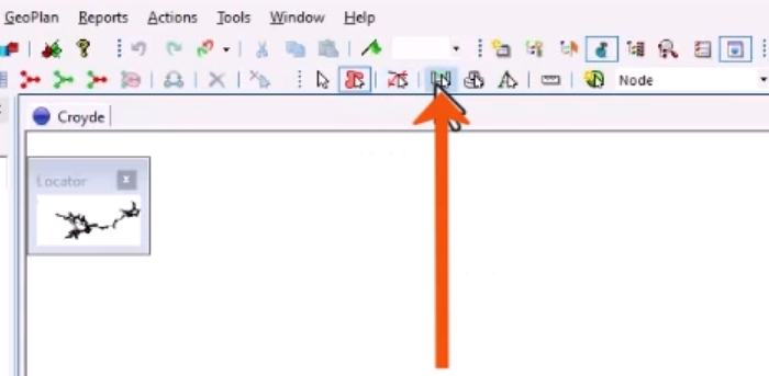
- Select an object on the GeoPlan, such as a pipe.
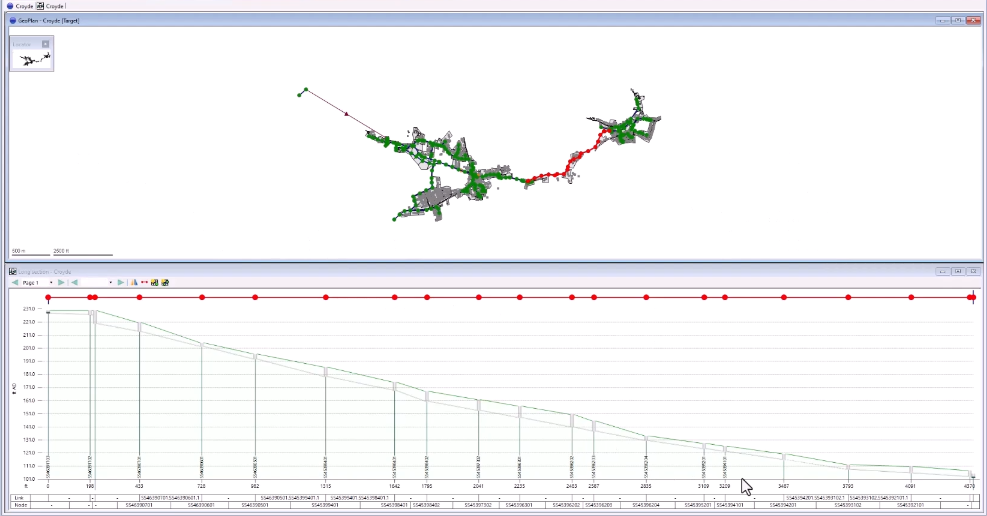
This populates the Long Section window from the selected pipe downstream, until a junction is reached.
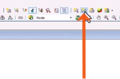
- Alternatively, if a selection is already made on the GeoPlan, from the Window toolbar, click New Long Section.
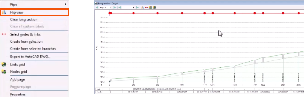
The layout for a Long Section window includes the level on the Y-axis and the length on the X-axis, as well as asset labels.

Several Long Section windows can be open at the same time, each with multiple pages.
On the toolbar:
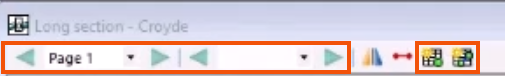
- Click the Next and Previous arrows to scroll through pages,.
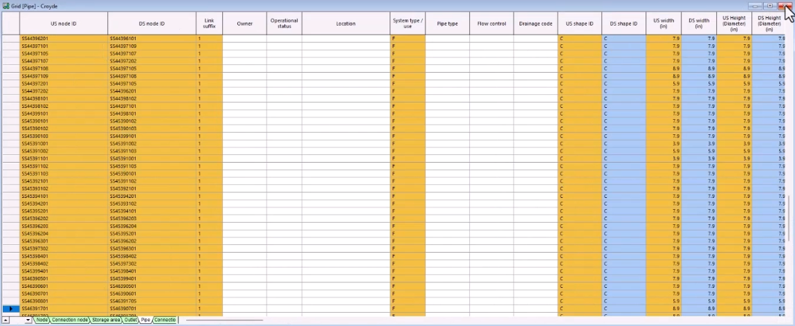
- Click New Nodes Grid or New Links Grid to open a grid of all nodes or pipes in the current Long Section page.
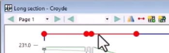
To select individual nodes or pipes, use the strip plan at the top of the Long Section window.
- Click a node or pipe in the strip plan to automatically select that object on the GeoPlan.
- To select multiple nodes or pipes, hold down CTRL while clicking additional objects.
- Double-click to open the Properties window for the selection.
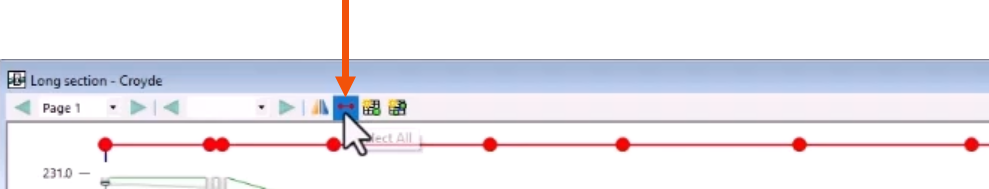
- Alternatively, from the Long Section toolbar, click Select All.
- For additional long section options, expand the Section menu or right-click the Long Section window.
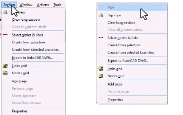
- To reverse the direction being viewed, right-click the Long Section window and select Flip view.
- To save the current Long Section window to DWG format, right-click and select Export to AutoCAD DWG.
- In the Export section data dialog, enter the appropriate information.
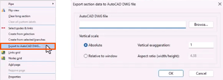
The Long Section can then be opened and viewed in AutoCAD.
To change the display:
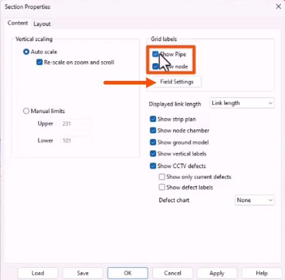
- Right-click the Long Section and select Properties.
- In the Section Properties dialog, for this example, select Show CCTV defects to show a symbol on the Long Section at the point where a CCTV defect has been recorded.
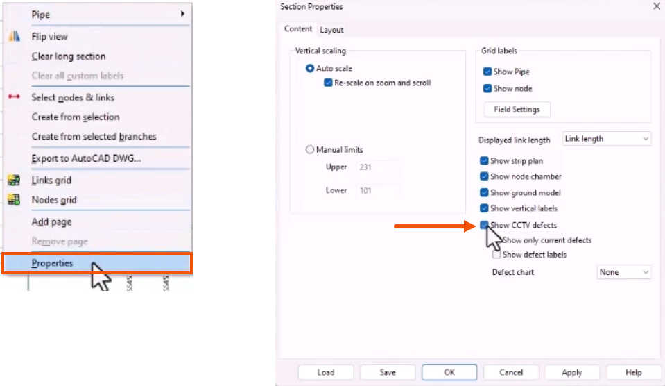
To show pipe and node custom labels at the bottom of the window:
- Under Grid label, confirm that Show Pipe and Show Node are selected.
- Click Field Settings.
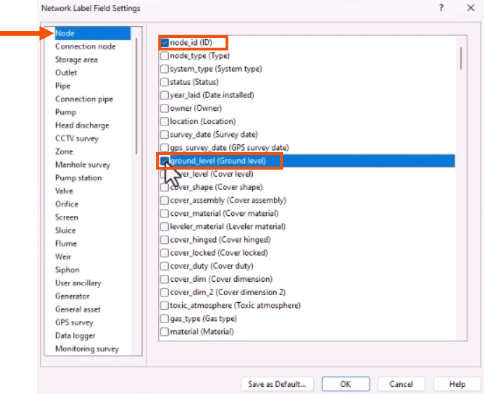
- In the Network Label Field Settings dialog, select Node.
- In the list of fields, select ground_level (Ground level) and node_id (ID).
- Repeat these steps for Pipe and select height (US Height (Diameter)) and length (Pipe length).
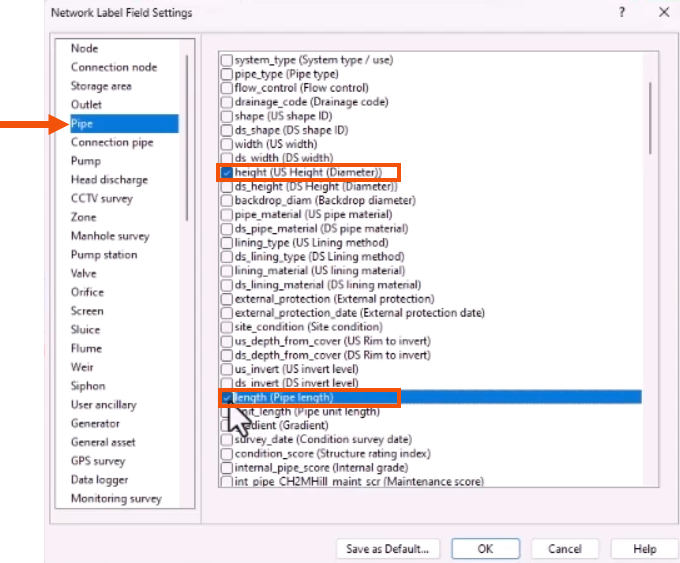
- Click OK twice to close the two windows.
The fields now display in grid labels in the Long Section window.
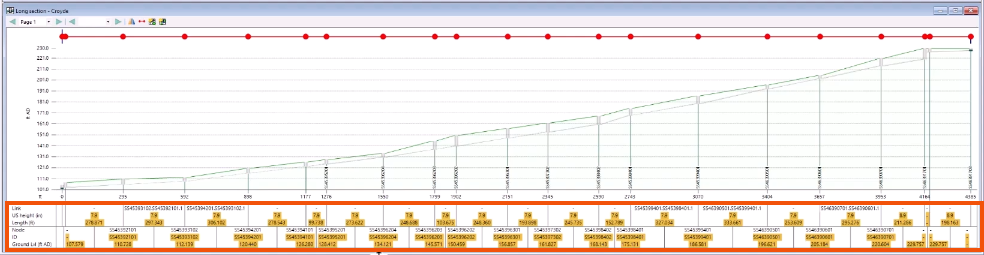
The display properties selected can be saved as the defaults.


