Access and edit 3D views in InfoAsset Manager
Step-by-step guide
In InfoAsset Manager, 3D views facilitate the review of asset data, particularly when looking at levels and connectivity.
- The 3D Network window displays the ground surface of a network that has a Ground Model loaded on its GeoPlan window.
- The 3D Manhole window displays an image of a selected manhole and connecting pipes as a 3D animation.
In this example, a network model and ground model are already loaded onto the GeoPlan.
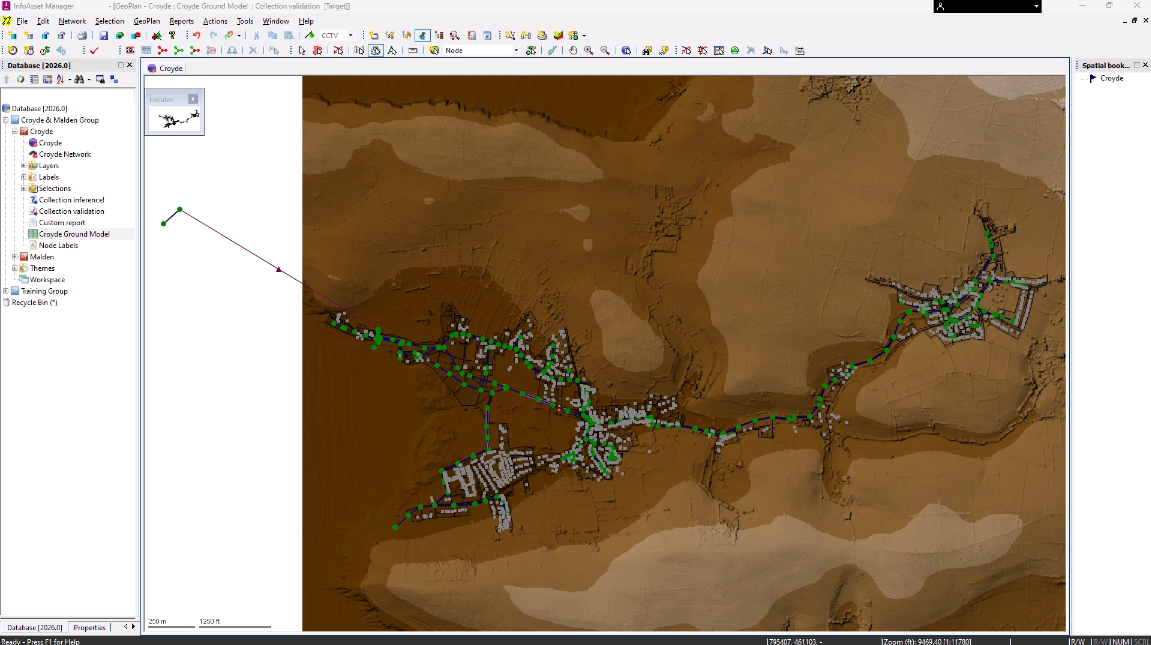
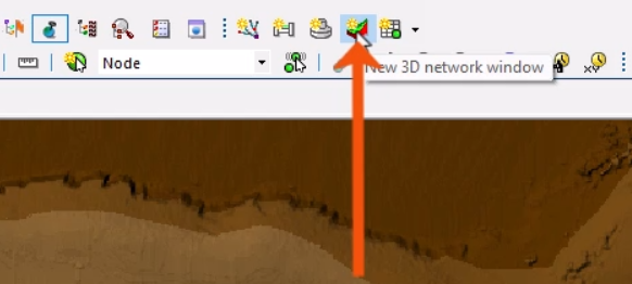
To create a 3D view of the network:
- On the Windows toolbar, click New 3D network window.
Note that it can take a bit of time to generate, depending on the amount of data.
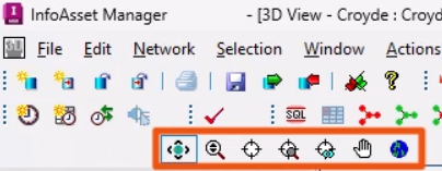
- To navigate the 3D view, use the mouse buttons or the 3D Navigation toolbar.
- Use the mouse scroll wheel to zoom in or out.
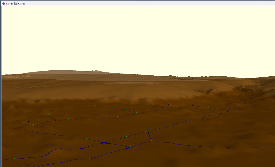
The view displays what would be seen by a person at the viewpoint, looking towards the center point.
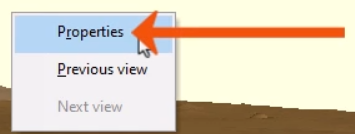
- Right-click the 3D view and select Properties.
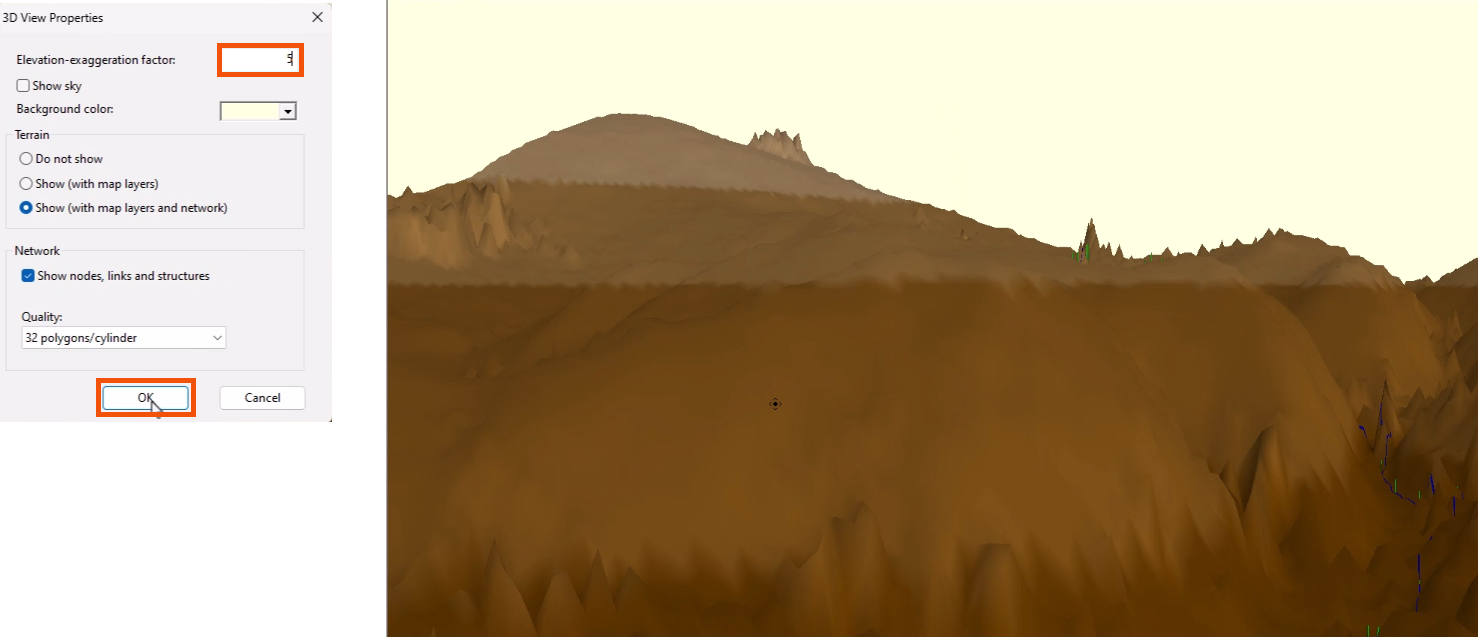
This opens the 3D View Properties dialog, with additional options to customize the view and toggle the display of terrain, network objects, and results.
- To make it easier to see variations in elevation when viewing a relatively flat ground model, set the Elevation-exaggeration factor—in this case, to 5.
- Click OK.
To display only selected objects in the generated 3D view window:
- In the GeoPlan, create a selection of objects.
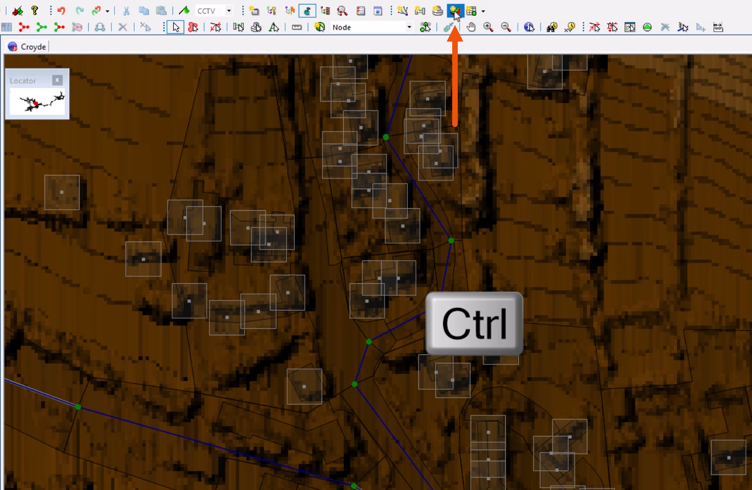
- On the Windows toolbar, click New 3D network window.
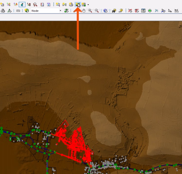
- To limit the creation extents to the objects within the current GeoPlan zoom extent, press and hold CTRL while clicking New 3D network window.
To open a 3D manhole window:
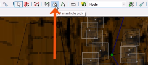
- From the GeoPlan Tools toolbar, click 3D manhole pick.
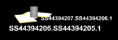
- In the 3D view, select a node.
A 3D manhole window opens to display a 3D view of the node.
Similar to navigating the 3D network window, use the mouse buttons or the 3D Navigation toolbar to move around the view.
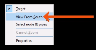
- Right-click the view to access more options, such as View From South.
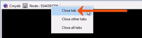
As a best practice, close 3D views as soon as reviewing is complete, as they require significant computer resources.
- To close the view, right-click the window tab and select Close tab.