& Construction

Integrated BIM tools, including Revit, AutoCAD, and Civil 3D
& Manufacturing

Professional CAD/CAM tools built on Inventor and AutoCAD
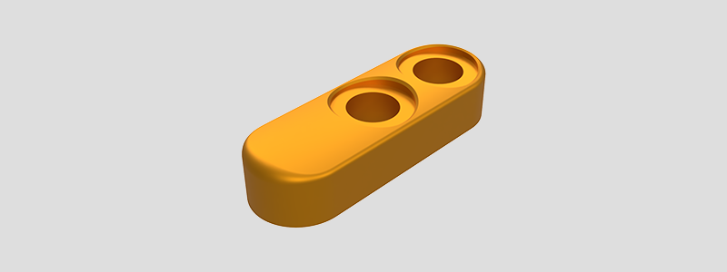
Set up, program and machine the flip chip of a concept motorcycle suspension linkage system.
Set up, program and machine the flip chip of a concept motorcycle suspension linkage system.

Project scenario:
A customer has asked your company to prototype a new suspension linkage concept for a current motorcycle. The suspension linkage assembly is comprised of two main links that are mirrored versions of each other, two flip chips that allow the leverage ratio to be adjusted and a heim joint end to be welded to an adjustable rod after manufacture. The customer has asked your company to create all the tooling, toolpaths and first article parts starting with the flip chip design.
These downloadable resources will be used to complete units in this module:
Teaching this project to students in the classroom?
Use this instructor guide to incorporate this and our other project parts into your lesson plans. You'll understand how to use CAD and CAM workflows to combine this and other projects into a motorcycle suspension linkage. Then, machine the parts using standard stock sizes.
Want to create custom learning playlists to share with your students?
Share modules and courses using Playlists. Once you create a Playlist, share the URL with your students and they can sign into their Autodesk Account to access. Choose and share the modules that best fit your curriculum using the links below.
Need to teach the skills covered this project?
Send your students to our 3-axis milling self-guided courses. They can learn at their own pace, track their own progress, and earn a certificate of completion when they get 75% or more on the final test.
Machining best practices supports you in the CNC machining of the motorsport suspension flip clip. Review the process plan and cutting data for general guidelines to support you in this project. The sample setup sheet provides information about how the part was machined. Post machining, inspect your part while reviewing the supplied detailed drawing, and populate the inspection report to verify acceptable part tolerances.