This article examines the challenge of designing a factory layout without knowing how it will perform under real operating conditions. It explores how Autodesk Factory Design Utilities and Autodesk FlexSim work together to give engineering teams an end-to-end digital factory planning workflow, from spatial design to operational validation.
Building a factory can be one of the most consequential investments for a manufacturer. Wrong decisions, such as installing equipment in the wrong sequence or routing a conveyor through a bottleneck, can be costly to fix once a plant is built. As a solution, Autodesk Factory Design Utilities and Autodesk FlexSim give design teams a way to validate their layouts and operational assumptions before the build begins.
Factory layout planning without visibility
Historically, factory designers have relied on static, two-dimensional drawings of their floor plans when entering the construction phase. But in reality, this approach falls short, as factory layout planning is more complex than any static drawing can capture. Where designers need to account for building footprint, equipment placement, aisle widths, material routing, and staffing zones, two-dimensional drawings and manual walkthroughs only tell designers whether equipment fits within a floor plan, not how a factory will actually perform.
For example, consider a shared inspection area where two assembly lines meet. Even if designers sized the workstations correctly on a static floor plan, these two lines might cause congestion the moment they run at full capacity. Finding these issues after commissioning means remediation at the full construction cost.
Manufacturing systems are dynamic, and designers need tools that reflect this truth. Without a way to test how the system performs over time, with real variability and real operational logic in the model, design teams are forced to make assumptions in their design. To overcome this challenge, they need a tool that tests the full system behavior before production.
From layout design to operational validation
Autodesk Factory Design Utilities gives designs the tools they need to build accurate, data-rich factory layouts in both 2D and 3D.
To start, designers can use AutoCAD and Autodesk Inventor to create layouts directly from a shared asset library, which includes conveyors, robots, racks, and workstations. The two tools are bidirectionally synchronized, meaning any change a designer makes to the floor plan in AutoCAD (2D) will update immediately in Inventor’s assembly (3D). In that way, teams always have a single, consistent layout throughout their planning process.
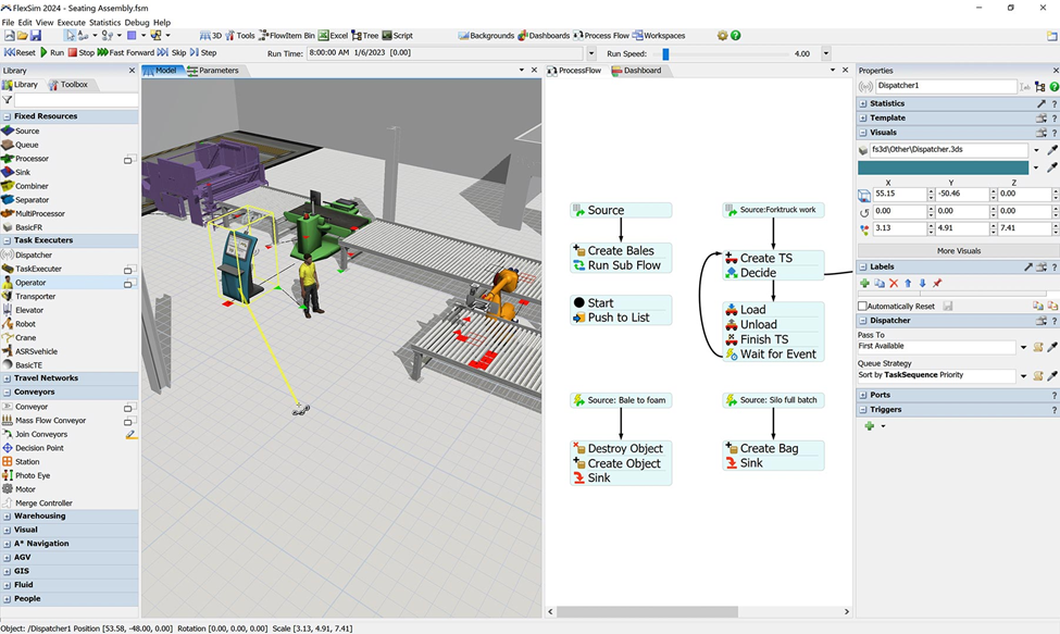
When designers need to evaluate their layout’s theoretical performance, Autodesk FlexSim offers a powerful 3D discrete-event simulation (DES) platform that can model production processes, material flow, and logistics as sequences of time-based events. Using drag-and-drop model construction and a code-free logic environment, engineers can use the tool to build detailed simulation models directly on top of their Factory Design Utilities layouts.
With a FlexSim simulation running against a validated layout, engineers get deeper insights into their design that static tools can’t provide. What happens to throughput if an assembly station goes offline? Which layout option minimizes travel time? Teams can use FlexSim’s scenario and experiment manager to evaluate these questions side by side, compare results through built-in performance dashboards, and garner data-backed insights into their proposed design.
Build what you intended
As factory production becomes more complex, the stakes of layout decisions rise as well. Working together, Autodesk Factory Design Utilities and FlexSim give design teams spatial and operational accuracy in a connected workflow. Designers can test more configurations, identify constraints before they become expensive problems, and arrive at construction with confidence that the factory they are building will perform exactly as intended.
Factory layout planning is the process of organizing equipment, workflows, and physical space to support efficient production. A well-planned layout reduces bottlenecks, minimizes travel time, and helps ensure manufacturing processes run smoothly from day one.
2D layouts show where equipment fits in a space but do not reflect how a factory operates over time. They cannot model material flow, congestion, or variability, which are critical to understanding how the system performs under real production conditions.
Without simulation, teams rely on assumptions about throughput, capacity, and flow. This can lead to bottlenecks, underutilized equipment, or congestion issues that are costly to fix after construction and commissioning.
Manufacturers can validate layouts by combining 3D layout tools with simulation software. This allows teams to test different configurations, evaluate performance scenarios, and identify problems before physical construction begins.
Autodesk FlexSim uses a 3D simulation environment with drag-and-drop modeling and built-in logic to replicate production processes, material flow, and resource behavior. It allows engineers to test scenarios without needing to write code.
Engineers can evaluate throughput, identify bottlenecks, test downtime scenarios, and compare layout alternatives. Simulation provides data-driven insights into how design decisions impact overall factory performance.
Simulation allows teams to test different configurations and identify where delays occur. By adjusting layouts, workflows, or resource allocation in the model, engineers can optimize flow and improve throughput before implementing changes in the real factory.