This post is also available in:
Learn everything you need to know about bodies and components in Autodesk Fusion!
Within a single Autodesk Fusion file, you can have a collection of parts that are all connected to an assembly. This means that regardless of how complex your design grows, you’ll always have one file and one design environment for your entire workflow. Sounds nice, right? This article and video tutorial cover everything you need to know about the structure that makes this system possible: bodies and components.
What are bodies in Autodesk Fusion?
Let’s start with the most simple of the two—bodies. In Fusion, a body is any continuous 3D shape. That might be a sphere, cube, cone, etc. Whenever you create a 2D sketch in Fusion and then extrude it into a 3D shape, you automatically create a body. The keyword about a body is that it has to be continuous. Take a cube and cut it in half, and you now have two bodies.
Bodies are great when you want to model an object that won’t require any associated motion. Maybe you decide to model a cup. This is a static object that won’t move and will likely consist of a collection of bodies, including a mug and handle.
There are several specific constraints you’ll want to know about bodies. Remember these:
- Bodies share the coordinate system and origin of your top-level assembly.
- If you copy and paste a body, changes you make to one body will not affect the other.
What happens when you make a body but realize you wanted it to be a component? This is a simple fix. Right-click the body in your Browser, and select Create Components from Bodies.
Elevate your design and manufacturing processes with Autodesk Fusion
What are components in Fusion?
In Fusion, a component is a part that is capable of motion and has its own unique origin. A component can also serve as a container for a variety of design objects, including:
- Bodies
- Sketches
- Construction geometry
- Decals
- Other components
Components are great for both organization and design reuse.
Like bodies, there are several constraints to keep in mind when using components:
- Every component has a unique timeline.
- Every component has a unique origin and coordinate system.
- Every component has a unique part name, number, and description that will show up in your parts list.
- If you copy and paste a component, changes made to one component will affect the other depending on the paste command.
Overall, anytime you plan to design an assembly or subassembly with parts that will have motion, you will need to create those parts as components.
Other ways to understand bodies and components
It might be easier to understand the relationship between bodies and components by viewing them in a tree-like structure, as shown below:
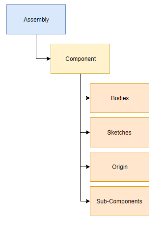
Here we can see a clear parent-child relationship unfolding. The assembly sits at the top of our design hierarchy and can contain one or multiple components. Components can contain one or multiple bodies, including other design objects like sketches, construction geometry, etc.
Prefer a table to compare these two concepts side by side?
| Body | Component | |
| What it is | Any continuous 3D shape, e.g. cylinder, sphere, etc. | Acts as a part within an assembly and/or a container for other design objects |
| When to use it | For static models | For assemblies that require movement between parts |
| Origin/Coordinates | Same as assembly | Each component has unique origin/coordinates |
| Motion | No | Yes, with joints |
| Manufacturing | Will not show up in parts list or drawing | Shows up in part list/drawing, each component has a unique part name, number, description |
| Copy/paste behavior | Changes to a copied body do not affect the original body | Changes to a copied component can affect the original component |
How components are named
Another thing to note is how components are named in the Browser. When you copy and paste a component with the standard Paste command, these two components are linked together. Make a change to one, and it will change the other.
The number/semicolon structure can identify these connected components after their name. For example, Pulley 1:2 is the 2nd instance of the 1st pulley, which is Pulley 1:1.
If you copy and paste a component with the Paste New command, then your new component will not be linked with the original.
Components and the timeline
One important feature that components have is their own unique timeline. Hover over a component in your browser and select the radial button to activate it.
Now take a look at your Timeline at the bottom of the canvas and notice that the history is different. The history that you see here is specific to the component that you just activated. Activate your top-level assembly, and your Timeline will switch to its default view.
This is an important distinction to make. When building out the features for a specific component, it’s common for designers to activate the component first and then start working on it. This helps to keep component-specific changes nested within their own timeline.
Put your bodies and components skills to the test
There you have it! That’s everything you need to know about the basics of bodies and components in Autodesk Fusion. Components are an extremely versatile tool that can keep even the most complex projects organized by housing-related sketches, joints, components, and other objects in one convenient location. Plus, using components allows you to easily reuse individual parts of your design in other projects without reinventing the wheel.
If there’s only one thing you remember about bodies and components, it’s this: components have motion, and bodies do not. Just making a static object? Bodies will do. Planning to make an assembly with moving parts? Start with components first. You can learn the rest of the details as you go.