This post is also available in:
Here are the top things you should know about Fusion electronics. Even if you’re already using the workspace, you may learn something new.
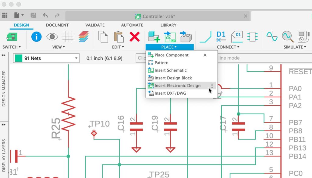
Fusion electronics is a dedicated workspace within Autodesk Fusion that provides integrated tools for PCB design, schematic creation, and electronics engineering within a unified CAD environment that bridges electronic computer-aided design (ECAD) and mechanical computer-aided design (MCAD) workflows. Unlike standalone PCB tools, Fusion electronics integrates ECAD and MCAD in a single cloud-based platform, eliminating file conversion and data translation issues.
Fusion includes a dedicated electronics workspace that caters to the needs of electronics engineers working on projects of any size. Fusion electronics offers an extensive suite of tools and resources tailored for PCB design and provides a seamless transition from 2D circuit board layout to a functional PCB 3D model.
Quick Fusion electronics feature overview
Here are the 17 key features covered in this article:
- Cross-disciplinary team collaboration with ECAD/MCAD integration
- EAGLE design import capability
- Real-time schematic and PCB synchronization
- Electronic design automation (EDA) tool integration
- Design rule checking (DRC) for PCB layouts
- SPICE simulation for circuit validation
- Autorouter for automated trace routing
- Differential pair routing for signal integrity
- Electronic library component editor with IPC-compliant calculators
- PCB manufacturing file export (Gerber, ODB++)
- Design variant management
- Polygon copper pour for power planes
- Push and shove routing
- Multiple signal simultaneous routing
- Quick route toolset
- Temperature cooling simulation
- Manual routing with three routing modes
Key specifications
| Category | Details |
|---|---|
| Supported Export Formats | Gerber, ODB++ |
| Compatible Import Sources | Autodesk EAGLE |
| Simulation Types | SPICE (base subscription), Signal Integrity (extension required), Temperature/Cooling (extension required) |
| Routing Modes | Full Manual, Walk Around, Push and Shove |
| Workspace Limits | Up to 999 schematics, 16 signal layers, unlimited board area |
Collaboration & integration features
What cross-disciplinary collaboration tools does Fusion offer?
Fusion provides real-time design sharing, in-context commenting, and seamless ECAD/MCAD integration for unified team collaboration.

Before we dig into electronics-specific features, it’s important to understand collaboration tools in Fusion. As a whole, Fusion is equipped with sophisticated collaboration functionalities instrumental in cross-disciplinary team engagement. It integrates electronics design tools with mechanical design, simulation, and manufacturing capabilities, thus providing a fluid, consolidated, and efficient design process.
Teams can share design files, leave comments within designs, and provide in-context feedback in real-time. This creates a conducive atmosphere for effective communication, ensuring the design process remains synchronized and enhances the confidence that products will meet desired specifications.
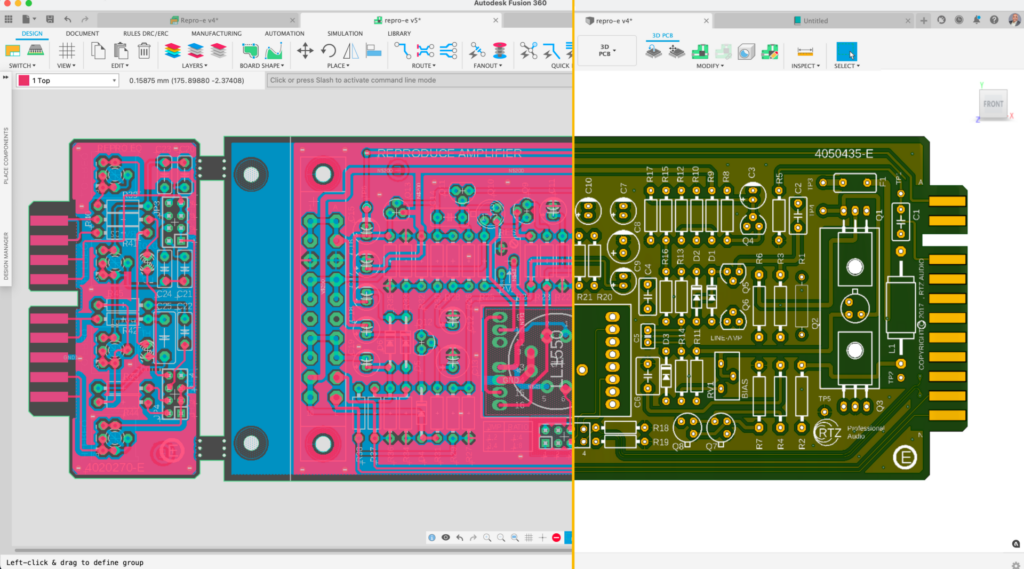
Digging even deeper into collaboration, Fusion provides seamless integration between MCAD and ECAD tools. This integration allows engineers to design PCBs within the context of the entire product, ensuring better collaboration and optimized product development. Changes in one domain are automatically reflected in the other, ensuring a synchronized design process. Learn more about how Fusion makes electronics to mechanical workflows easy with seamless ECAD/MCAD integration.
Can Fusion import EAGLE designs?
Yes, Fusion can import design and library files created using Autodesk EAGLE.
Fusion can assimilate design and library files created using Autodesk EAGLE. We have strategically incorporated the expansion of our import capabilities into our development roadmap to include files from a broader range of applications. Learn more about migrating from EAGLE to Fusion electronics here.
How does Fusion keep schematics and PCBs synchronized?
Fusion maintains a real-time bidirectional link between schematic designs and PCB layouts, instantly reflecting changes across both views.
Fusion offers a seamless design experience by maintaining a real-time link between the schematic design and the PCB layout. Any changes you make to the schematic are instantly reflected in the PCB layout, ensuring consistency and preventing conflicts. This synchronized workflow enables designers to work more efficiently, reduces the chances of errors, and significantly speeds up the design process.
4. What EDA tool integration does Fusion support?
Fusion integrates with leading Electronic design automation (EDA) tools, enabling engineers to bridge schematic design and PCB layout with mechanical design and simulation.
Fusion offers an advanced level of integration with leading EDA tools, enabling electronics engineers to utilize their preferred EDA software within the sophisticated environment offered by Fusion. This harmonious integration establishes a fluid workflow, bridging schematic design and PCB layout in EDA tools to mechanical design and simulation. The result is a consolidated, efficient electronics design process.
Design rule & constraint tools
5. What is design rule checking (DRC) in Fusion?
Design rule checking (DRC) is a feature that validates PCB layouts against manufacturing constraints such as trace clearances, layer stack-up specifications, and material assignments in real-time during the design process.
Fusion includes real-time PCB layout DRC functionality. This feature empowers electronics engineers by facilitating the definition and enforcement of design principles during the design process and not as a post-process task. Ensuring designs adhere to manufacturing constraints and specifications, such as layer stack up with material assignment, clearances, and much more. The DRC utility within Fusion aids in detecting potential issues within PCB layouts, thus guaranteeing the production of high-quality, manufacturable designs.
How does Fusion handle design variants?
Fusion’s schematic editor allows you to create and manage design variants, enabling you to repurpose a schematic for different PCB variants without creating a new one from scratch.
The schematic editor allows you to create and manage design variants. This feature provides the flexibility to repurpose a schematic for different PCB variants without creating a new one from scratch. You can easily define and switch between various component values and part numbers or even enable and disable components per the requirements of different product variants.
How do you define power planes in Fusion?
Fusion supports polygon copper pouring, which allows you to define power planes that automatically connect to assets with matching names while respecting DRC constraints.
Fusion electronics supports polygon copper pouring. Polygon copper pours on a PCB are crucial as they efficiently manage power distribution, thermal dissipation, and ground connections, thereby enhancing the overall performance and reliability of the electronic device. The polygon’s shape can be defined manually or by selecting the PCB outline. The polygon will automatically connect to assets with the same name as the polygon if it doesn’t violate the DRC constraints.
Simulation & analysis
What SPICE simulation capabilities does Fusion offer?
Fusion’s schematic workspace includes SPICE simulation capabilities that validate expected circuit performance by simulating any valid SPICE circuit.
The electronics schematic workspace SPICE simulation capabilities facilitate validating the expected performance of the electronic circuit. By integrating SPICE simulation, you can simulate any valid SPICE circuit, ensuring that your schematic design results align. This feature enables you to assess and verify the electronic designs’ functionality.
Can you perform temperature simulations on PCBs in Fusion?
Yes, Fusion offers temperature cooling simulation for PCBs through the Cooling extension (requires separate subscription), allowing you to identify heating issues and assess cooling scenarios including fan placement.
Fusion offers a temperature cooling simulation capability for PCBs through the cooling extension. With the extension enabled, you can conduct cooling solutions to identify heating issues within their designs. You can effectively assess how their PCBs will respond under various cooling scenarios, including using cooling tools like fans.
Routing & layout capabilities
Does Fusion have an autorouter?
Yes, Fusion includes an autorouter that automates routing of complex electronic circuits following your DRC manufacturing preferences, with adjustable effort levels for multiple routing results.
Fusion electronics includes an autorouter, a powerful tool that automates routing complex electronic circuits following your DRC manufacturing preferences. You can select a particular signal(s) or the entire board to be Autorouted. The level of effort set will determine the number of results you can choose from when completed.
What is differential pair routing in Fusion?
Differential pair routing is a technique that protects key signals from common-mode noise by routing paired traces at the same length, with fine-tuning available through the Meander command.
Differential pair routing is a technique developed to protect key signals in your design from common-mode noise. Fusion 360 includes Differential Pair routing for traces that require the same length. By invoking the Meander command, you can fine-tune the length of your Differential Pair.
What is push and shove routing in Fusion?
Push and shove routing automatically moves existing traces and vias to make space for new routes or components while respecting manufacturing constraints.
Fusion’s push and shove capabilities offer a more advanced and interactive approach to PCB signal routing. This tool moves existing traces and vias to make space for new ones, enhancing the efficiency of the routing process. Furthermore, this feature also extends to the placement of new components. When a new part is added to the layout, Fusion will attempt to adjust the existing traces and vias to accommodate the component.
Can you route multiple signals simultaneously in Fusion?
Yes, Fusion offers fully manual, automatic, and interactive routing options for handling multiple signals simultaneously.
Fusion offers many options for handling multiple signal routing. The fully manual capability gives you complete control over the path of the signals, offering maximum customization. Then there is the automatic routing feature, where Fusion takes over and routes the selected traces independently. Lastly, there’s an interactive option where Fusion tries to route the group based on a predefined path, balances automation, and manual control.
What is the quick route toolset in Fusion?
Quick route is a comprehensive toolset that improves routing efficiency by offering interactive completion during manual routing—press ‘Enter’ and Fusion automatically completes the route while following design constraints.
Quick route in Fusion is a comprehensive toolset that drastically improves routing efficiency on a PCB. It offers multiple options catering to unique needs and preferences. For instance, one can use quick route interactively during manual routing. While manually routing, you can press ‘Enter’ and Fusion will follow the defined design constraints, navigate around obstacles, and automatically complete the route. Additional options of quick route allow you to select and route individual signals and much more.
What routing modes are available for manual routing in Fusion?
Fusion offers three routing modes: Full manual, walk around, and push and shove, each providing different levels of control and automation.
| Routing Mode | Description | Ideal Use Case |
|---|---|---|
| Full Manual | Gives absolute control over routing, including the ability to override DRC violations | When you need complete control and are willing to manually manage constraint compliance |
| Walk Around | Ensures adherence to manufacturing constraints and automatically navigates around obstacles | Standard routing where you want automatic obstacle avoidance with DRC compliance |
| Push and Shove | Routes signals while moving existing traces and vias out of the way, respecting manufacturing constraints | Dense boards where you need to fit new routes among existing traces |
Library & manufacturing tools
What library tools does Fusion provide?
Fusion includes a comprehensive library editor with IPC-compliant calculators that can build footprints with 3D models by transferring details from component specification sheets.
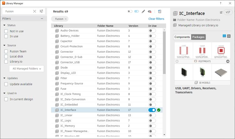
Fusion has a comprehensive set of libraries developed by our team and partners to meet various design needs. Should you find the necessity to create custom parts, the Library Editor within Fusion 360 is reliable and user-friendly. It includes IPC-compliant calculators that can build your footprint with 3D models in moments; you only need to transfer the details from the asset specification sheet to the calculator template.
What file formats can Fusion export for PCB manufacturing?
Fusion can export PCB manufacturing files in industry-standard Gerber format and ODB++ format.
Fusion includes a few options for exporting manufacturing files from your PCB, including industry-standard formats like Gerber and ODB++ formats.
Frequently asked questions about Fusion electronics
What file formats can Fusion export for PCB manufacturing? Fusion exports PCB manufacturing files in industry-standard Gerber and ODB++ formats.
Does Fusion have an autorouter? Yes, Fusion includes an Autorouter that automates routing of complex circuits following your DRC manufacturing preferences.
Can Fusion import EAGLE designs? Yes, Fusion can import design and library files created using Autodesk EAGLE.
What simulation capabilities are included in the base Fusion subscription? The base subscription includes SPICE simulation for circuit validation; Signal Integrity and Cooling simulations require separate extensions.
How many signal layers does Fusion electronics support? Fusion electronics supports up to 16 signal layers with unlimited board area.
Ready to get started with Fusion electronics?