Engineering teams can improve profitability by applying Design for Assembly (DFA) principles early in the development cycle. This article explores how technical strategies for part reduction and assembly simulation ensure efficient production. Autodesk Inventor provides professional tools to automate bill of materials and optimize complex mechanical designs, streamlining manufacturing.
Enhance Your Engineering Workflows
Precise, powerful, and ready for innovation with Autodesk Inventor.
Design for assembly (DFA) is an approach that simplifies product structures to guarantee assembly processes are efficient and cost-effective. By using DFA strategies to address assembly constraints during the initial modeling stage, designers can reduce the likelihood of downstream manufacturing errors, lower total part counts, and simplify assembly processes.
Ultimately, an effective DFA implementation leads to shorter production cycles and enhanced product reliability in complex mechanical systems. With tools like Autodesk Inventor, teams can maximize their DFA efforts with intelligent automation throughout the entire design lifecycle.
Frameworks for assembly optimization
Mechanical design teams commonly struggle to manage high part counts and intricate assembly sequences. In this context, the main goal of any assembly optimization is to minimize the total number of components and reduce material handling and inventory overhead.
To approach DFA, product teams can start by determining the functional necessity of each part to determine whether multiple components can be combined into a single complex geometry. With a reduced Bill of Materials (BOM) count, the supply chain is simplified and there are fewer interfaces where mechanical failure might occur. As part of this process, designers must also focus on symmetry and self-aligning features to guarantee that all consolidated parts fit together in only one possible orientation (i.e., without a chance of misassembly).
Implementing mistake-proofing techniques, such as Poka Yoke, prevents incorrect orientation during manual or automated assembly. For example, designers can create parts with notches, asymmetric holes, or chamfers that guide the component into the correct position. These techniques are powerful because they eliminate the need for custom jigs and reduce mental burden on assembly technicians.
Similarly, a designer’s choice of fasteners can greatly affect assembly speed. For example, snap fits and integrated locking mechanisms accelerate the build process more than threaded fasteners, such as screws or bolts.
In modern manufacturing and assembly, automated assembly environments require even stricter adherence to orientation and handling principles, as robotic grippers must easily access, pick up, and place components without interference. To this end, designers must evaluate each part’s center of gravity and grasping surfaces to maintain stability during high-speed motion. By standardizing component sizes and hardware throughout different product lines, organizations can achieve greater scalability and flexibility in their production workflows.
All things considered, these technical decisions directly influence the final cost and quality of the mechanical system.
Enhancing DFA workflows with Autodesk Inventor
Product designers can use Autodesk Inventor to implement comprehensive DFA strategies through advanced 3D modeling and analysis tools. This enables designers to validate the form and fit of every component before any metal is cut. Inventor also provides access to part-simplification features that identify opportunities to combine multiple components into a single part, reducing assembly complexity and minimizing the fasteners required for a stable build.
For example, using Inventor, engineering teams can perform interference detection to identify clashes between moving parts and static components. This detection also confirms each part has the necessary clearance for assembly tools and robotic grippers to operate. Designers can use the tool’s parametric design engine to establish relationships between components, so changes to one part automatically update all related assembly geometry. This automation also helps keep large-scale projects consistent and prevents manual coordination errors from propagating.
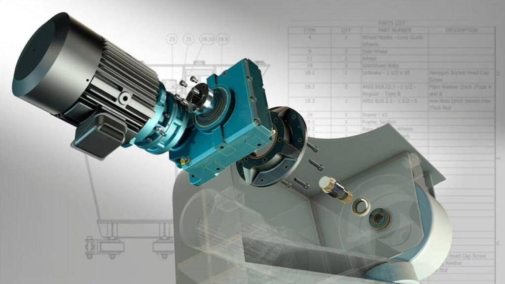
Teams also use iLogic in Inventor to automate the process of configuring complex assemblies based on specific functional rules. Using this automation, designers can generate product variations that automatically adhere to predefined assembly constraints and manufacturing standards. Inventor also automates BOM generation to help teams account for every part and fastener in the production schedule.
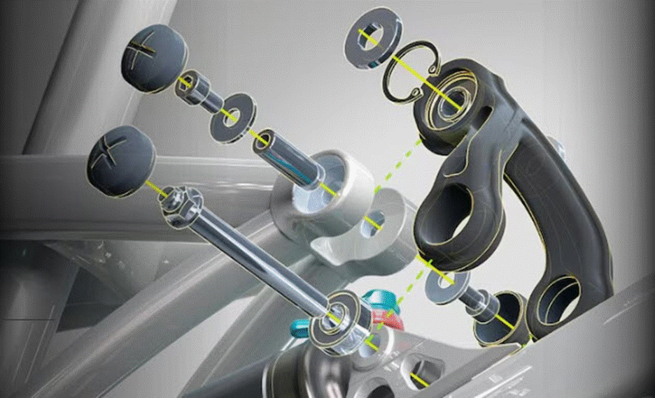
Additionally, manufacturing teams can use Inventor’s advanced visualization tools to create detailed assembly instructions and technical documentation. With these tools, engineers can produce exploded views and animated sequences that guide technicians through the correct assembly order on the shop floor.
Future-proofing production
Adopting a technical approach to assembly design keeps products viable in a competitive manufacturing industry. That’s why designers who prioritize simplicity and precision can create systems that are easier to build, maintain, and repair throughout their lifecycles. Luckily, professional engineering tools like Autodesk Inventor provide designers with the technical capabilities needed to handle complex assembly workflows.