 Shannon McGarry
GD&T is more than a design standard. It’s a foundation for inspection and quality control. Learn how it supports functional inspection, reduces quality risk, and connects design to manufacturing.
Enhance Your Engineering Workflows
Precise, powerful, and ready for innovation with Autodesk Inventor.

While geometric dimensioning and tolerancing (GD&T) is often introduced as a way to communicate design intent, its real power shows up downstream. In modern manufacturing, it’s a foundational tool for inspection and quality control, providing a precise, standardized way to verify whether parts will assemble, function, and perform as intended.
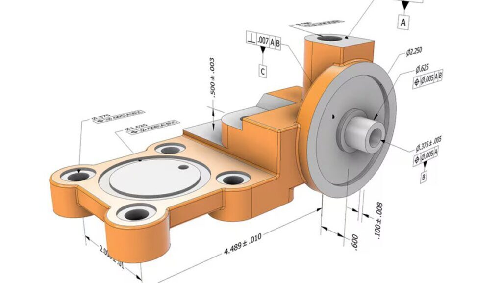
GD&T was built for inspection, not just drawings
Traditional plus/minus tolerancing answers a simple question: Is this feature the right size?
GD&T answers a more important one: Does this part actually work in the assembly?
By defining allowable variation in terms of form, orientation, location, and runout, GD&T establishes clear criteria for inspection—criteria that align directly with functional requirements. Standards such as ASME Y14.5 and ISO GPS exist specifically to ensure that designers, manufacturers, and quality teams interpret those requirements consistently.
How GD&T supports modern inspection workflows
GD&T enables inspection teams to evaluate parts against datum‑based tolerance zones, rather than isolated dimensions. This approach is essential for today’s quality environments, where inspection relies on:
- Coordinate Measuring Machines (CMMs)
- Portable measurement arms
- Optical and laser scanning systems
- Digital inspection reporting
Modern GD&T inspection has moved beyond simple pass/fail gaging toward numerical measurement and reporting, particularly for complex geometry and tight tolerances. This shift is reflected in current inspection standards and training focused on GD&T‑based measurement methods.
GD&T reduces quality risk across the lifecycle
When applied correctly, GD&T improves quality control in several critical ways:
- Ensures functional fit and assembly by controlling how features relate to one another
- Reduces ambiguity between design, manufacturing, and inspection teams
- Prevents false acceptance or rejection of parts that meet size requirements but fail functionally
- Supports repeatable inspection processes across suppliers and production sites
This is why GD&T inspection is standard practice in industries such as aerospace, automotive, medical devices, and industrial machinery.
Where Autodesk Inventor fits in
The effectiveness of GD&T in inspection depends heavily on how well it’s defined at the design stage.
Autodesk Inventor supports standards‑based GD&T annotations directly within the design environment, helping teams embed inspection intent early—rather than retrofitting it later. GD&T applied in Inventor communicates not just what to make, but how to verify it, improving alignment between engineering and quality.
By using consistent datums, feature control frames, and tolerance definitions, Inventor helps ensure that inspection teams are working from a clear, unambiguous source of truth—whether they’re inspecting against drawings or CAD‑driven workflows.
From design intent to inspection confidence
GD&T is not an afterthought for quality control. When inspection teams understand the geometric requirements defined by GD&T, they can validate parts based on how they function, not just how they measure. And when GD&T is applied consistently in tools like Autodesk Inventor, that intent carries cleanly from design through manufacturing and inspection.
The result is fewer disputes, fewer surprises, and higher confidence that parts leaving the factory floor will perform exactly as designed.
Conclusion
GD&T provides the geometric clarity that modern inspection demands, and when paired with professional‑grade design tools like Autodesk Inventor, it becomes a powerful bridge between design, manufacturing, and quality.
Quality doesn’t start at inspection. It starts with how you define the part.
GD&T frequently asked questions (FAQs)
GD&T creates a shared, unambiguous definition of part requirements, ensuring design intent is interpreted consistently by manufacturing and inspection. In Autodesk Inventor, GD&T applied directly to the model helps align all downstream stakeholders around a single source of truth.
Clear GD&T reduces guesswork by specifying functional tolerances up front, which minimizes rejected parts and measurement disputes. When GD&T is embedded in Inventor models and drawings, inspection teams can validate parts against design intent rather than assumptions.
GD&T enables inspection directly from the 3D model, supporting model‑based workflows where the CAD definition drives measurement. Autodesk Inventor supports model‑based definition (MBD), allowing GD&T and product manufacturing information to live with the geometry.
Autodesk Inventor provides professional‑grade tools for applying, managing, and validating GD&T within both 3D models and production drawings, helping teams define tolerances correctly before parts ever reach the shop floor or CMM.
Inspection can only verify what was defined; it cannot correct poor or incomplete design intent. By defining GD&T clearly in tools like Autodesk Inventor, quality is designed into the part from the start—making inspection a confirmation step, not a correction process.