 Melisa Kaner
ECAD MCAD collaboration connects electrical and mechanical design into a unified workflow, helping teams reduce rework, improve product fit, and accelerate time to market with Autodesk Fusion.

Elevate your design and manufacturing processes with Autodesk Fusion
If your electrical and mechanical teams are still passing STEP files back and forth, you already know the problem. Designs drift. Late-stage conflicts show up in enclosures, connectors, and clearances. And every “small update” turns into another round of rework.
ECAD–MCAD collaboration isn’t just about sharing files. It’s about maintaining alignment between two disciplines that define the same product from different perspectives. When it works, teams iterate faster and catch issues earlier. When it doesn’t, integration becomes the bottleneck.
What’s changed in 2026 is how that collaboration happens. Connected environments are replacing file-based handoffs—and the difference shows up immediately in cycle time, rework, and design confidence.
What is ECAD MCAD collaboration?
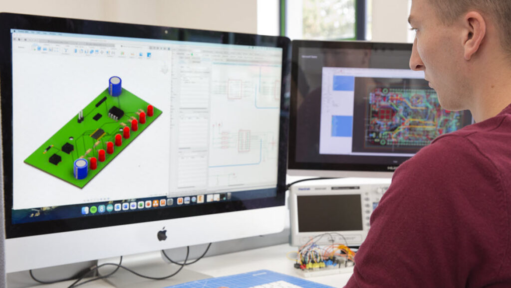
ECAD MCAD collaboration refers to the integration between electrical design workflows (PCB layout, schematics) and mechanical design workflows (enclosures, assemblies, product form).
This means:
- Electrical and mechanical teams working from shared geometry and constraints
- PCB designs fitting correctly within mechanical enclosures
- Changes in one domain updating and informing the other
Instead of working in silos, both disciplines operate within a connected design process.
Why file-based ECAD-MCAD workflows break down
- Changes are not continuous—they’re packaged and handed off
- Mechanical context is often outdated between exchanges
- Issue detection happens late, when fixes are expensive
- Ownership becomes fragmented across tools
What changes with a connected approach
- Electrical and mechanical changes stay visible in context
- Iterations happen continuously, not in batches
- Conflicts surface earlier in the design cycle
- Teams spend less time translating between tools
Why ECAD MCAD collaboration matters more than ever
As products become more compact and complex, the margin for error shrinks. Decisions made in one domain directly affect the other.
For example:
- A PCB that grows by a few millimeters may no longer fit the enclosure
- Thermal considerations in electronics impact mechanical material choices
- Connector placement affects usability, assembly, and product design
Without close coordination, these issues are often discovered late, when they are more expensive to fix.
The cost of poor ECAD MCAD integration
When workflows are disconnected, teams often rely on manual handoffs, incomplete data, or outdated models. This leads to predictable problems, including:
1) Late-stage design conflicts
Mechanical teams finalize enclosure geometry before PCB constraints are fully understood, leading to fit issues and redesign cycles.
2) Increased rework and iteration
Changes in one system require manual updates in another, often causing version mismatches and delays.
3) Slower time to market
Because issues are caught late, validation cycles stretch longer and product launches slip.
4) Reduced product quality
Disconnects between electrical and mechanical design can introduce reliability issues, especially in thermal performance, tolerances, and assembly.
What effective ECAD MCAD collaboration enables
When collaboration is built into the workflow, teams can design with full context from the start.
- Better spatial coordination: PCBs, connectors, and components are designed with enclosure constraints in mind from day one.
- Faster iteration cycles: Changes to board layouts or mechanical geometry can be validated immediately, reducing back-and-forth.
- Fewer physical prototypes: Virtual validation replaces trial-and-error, helping teams catch issues before manufacturing.
- Improved product performance: Thermal behavior, clearances, and assembly constraints are addressed earlier, leading to more robust designs.
Where traditional workflows fall short
Historically, ECAD and MCAD tools were separate environments, connected only through file exports like STEP or IDF.
This approach introduces friction, where:
- File exchanges are manual and easy to mismanage
- Updates are not synchronized
- Design intent is often lost in translation
This creates a lag between disciplines, exactly where errors tend to emerge.
The shift toward unified design environments
To solve these challenges, teams are moving toward integrated workflows where both domains operate within a shared environment.
Instead of exporting files back and forth:
- Mechanical and electronic designs reference the same data
- Updates propagate more reliably
- Teams can collaborate earlier in the process
The goal is file compatibility and continuous alignment between systems.
Why this matters for modern product design
This shift becomes even more important in industries like:
- Consumer electronics (tight packaging constraints)
- Automotive (electronic systems integrated into mechanical assemblies)
- Industrial equipment (complex assemblies with embedded electronics)
In these environments, success depends on how well teams can:
- Coordinate across disciplines
- Respond to change quickly
- Validate designs before production
Autodesk Fusion for ECAD MCAD
Autodesk Fusion addresses this challenge by bringing ECAD and MCAD workflows into a single, connected design environment.
Instead of relying on disconnected tools and manual file exchanges, Fusion enables:
- Integrated PCB design and mechanical modeling
- Shared geometry between electronics and enclosure design
- Real-time updates across disciplines
- Unified workflows from concept through production
This allows teams to:
- Design PCBs in the context of the full product assembly
- Identify clearance and fit issues early
- Iterate faster without losing alignment between domains
Electrical and mechanical decisions happen together, not in sequence.
What are you waiting for? Try Autodesk Fusion for free today to see how to bring your ECAD MCAD workflows together seamlessly.
ECAD MCAD collaboration – frequently asked questions (FAQs)
ECAD MCAD integration is important for PCB manufacturing because PCB designs must physically fit and function within a mechanical enclosure. Without integration, issues like misaligned connectors, clearance violations, or thermal problems are often discovered late, leading to costly redesigns and delays.
With integrated workflows in Autodesk Fusion, PCB layouts and mechanical models share the same design context. This allows teams to validate fit, form, and function earlier, reducing manufacturing errors and improving first-pass success.
ECAD (Electronic Computer-Aided Design) is software used to design electronic systems, including schematics, PCB layouts, and circuit behavior. It defines how components are connected electrically and how a board is physically routed.
In Autodesk Fusion, ECAD capabilities are built into the same environment as mechanical design, allowing PCB development to happen alongside the full product design rather than in isolation.
MCAD (Mechanical Computer-Aided Design) is software used to design the physical aspects of a product, including enclosures, assemblies, and mechanical components. It defines shape, fit, and structural behavior.
In Autodesk Fusion, MCAD and ECAD exist in the same environment, allowing mechanical designs to be developed alongside PCB layouts, ensuring both domains stay aligned from concept to manufacturing.
ECAD MCAD refers to the combined workflows of electronic design (ECAD) and mechanical design (MCAD) within a product development process. It ensures that electronics and physical components are designed together, not separately.
In Autodesk Fusion, ECAD and MCAD are integrated into a single platform, so PCB layouts, enclosures, and assemblies all reference the same data and stay aligned throughout the design process.
ECAD and MCAD teams work together by sharing design data, constraints, and updates throughout development. This typically includes:
-PCB geometry and component placement shared with mechanical designers
-Enclosure constraints influencing board size and layout
-Ongoing updates between teams as designs evolve
In traditional workflows, this happens through file exchanges. In Autodesk Fusion, updates are managed in a shared environment, so both teams can work against the same design and stay synchronized with fewer handoffs.
ECAD MCAD collaboration solves several common product development challenges:
–Design conflicts: Prevents mechanical interference and fit issues between PCBs and enclosures
–Data mismatches: Reduces errors caused by outdated or manually exchanged files
–Late-stage rework: Identifies issues earlier in the design cycle
–Slow iteration cycles: Keeps teams synchronized so changes don’t stall progress
These issues often arise when ECAD and MCAD tools operate in silos, increasing the risk of errors and delays.
ECAD MCAD collaboration reduces rework by enabling early validation and continuous synchronization between disciplines.
Instead of discovering problems after prototyping, teams can:
-Check PCB fit within enclosures during design
-Validate clearances and component placement in 3D
-Catch conflicts before manufacturing
With Autodesk Fusion’s integrated environment, updates to the PCB or mechanical design are reflected more consistently across the system, reducing the need for repeated redesign cycles.
ECAD-MCAD collaboration is the process of synchronizing electrical design (PCB layout and schematics) with mechanical design (enclosures, clearances, and assemblies) so both domains can evolve together without conflicts.
It helps teams catch fit, clearance, and integration issues earlier in the design process. Without it, problems often surface during late-stage integration, leading to rework, delays, and higher product development costs.
They typically communicate through file exchange (such as STEP or IDF files) or through integrated workflows that synchronize design data between systems. More modern approaches reduce reliance on file-based handoffs by maintaining shared design context.
File-based workflows introduce delays, versioning issues, and loss of context between updates. Changes must be manually exchanged, which increases the risk of misalignment between electrical and mechanical design teams.
It refers to workflows where electrical and mechanical changes can be reflected more continuously, reducing the need for manual file exchange and helping teams stay aligned as designs evolve.
A unified environment reduces translation steps between tools, improves visibility across domains, and allows teams to iterate faster with fewer integration issues.
Key capabilities include:
-Clear visibility of 3D board and enclosure context
-Reliable change tracking and propagation
-Flexible collaboration workflows
-Reduced dependency on manual file exchange
Consumer electronics, industrial equipment, automotive, aerospace, and any product development environment where electronics must fit within mechanical constraints.
Most ECAD-MCAD integration challenges emerge during data handoffs, when electronics, mechanical, and product lifecycle information are managed in separate systems.
Autodesk Fusion helps reduce those disconnects by bringing electronics design, mechanical design, data management, and collaboration into a connected platform. Through integration with Fusion Manage, teams can extend product data into PLM workflows such as BOM management, change management, release processes, supplier collaboration, and quality management while maintaining a shared source of product information.
Fusion Manage is also designed to integrate with enterprise business systems through open APIs, allowing manufacturers to connect PLM processes with ERP and other operational systems. This helps organizations share product and BOM information across departments, improve traceability, and reduce the risks associated with disconnected product data.
ECAD-MCAD integration can support compliance and quality processes by helping teams validate designs, maintain product data, and generate manufacturing outputs from a connected design workflow.
Autodesk Fusion includes Design Rule Check (DRC) capabilities that help engineers identify potential PCB layout issues before manufacturing, along with tools for generating PCB manufacturing outputs such as Gerber files.
Fusion also helps teams keep electronics and mechanical designs aligned through ECAD-MCAD collaboration, reducing the risk of discrepancies between PCB layouts and product enclosures as designs evolve. Combined with data management and PLM workflows available through Fusion Manage, organizations can better control revisions, manage change processes, and maintain traceability across product development.
Organizations with specific regulatory requirements such as IPC, RoHS, REACH, medical device, aerospace, or automotive standards should verify compliance requirements against their own processes and validation procedures.
As electronics products become more compact and mechanically constrained, coordination between PCB and mechanical design becomes increasingly important. Autodesk Fusion helps teams collaborate across electronics and mechanical workflows by connecting PCB design, 3D visualization, and mechanical design in a single product development environment. Engineers can review PCB layouts in the context of mechanical assemblies, helping identify potential fit, clearance, and integration issues earlier in the design process.
Fusion’s ECAD-MCAD integration helps keep electronics and mechanical designs aligned as products evolve. Rather than relying on disconnected files and manual communication, teams can work from connected design data, reducing the risk of enclosure conflicts, component placement issues, and late-stage design revisions.
For organizations developing increasingly complex products, this connected workflow can improve collaboration, reduce design iterations, and help accelerate the transition from electronics design to manufacturing. Fusion also combines electronics, mechanical design, simulation, manufacturing, and data management capabilities on a shared platform, helping teams maintain a more complete view of product development.