 Annaka Ketterer

September brings new Scene Lights, expanded sheet metal and PMI workflows, faster performance, and more. Explore everything new in this update.
Minor Update
Our latest minor update brings several important fixes and improvements to enhance your experience. Click to learn more.
V.2705.1.30 – October 5, 2026
Design
- We improved stability when orbiting and interacting with models in the 3D canvas while Slice is enabled in the Sketch Palette or a Section Analysis is active. Fusion no longer crashes when using Sketch Slice or working with transparent bodies in a section analysis.
- We resolved an issue where motion links stored in an externally referenced subassembly were not always applied in the top-level assembly after changing configurations or reopening a design. Affected components could move freely instead of following their linked motion. Motion links, joints, assembly constraints, and related relationships that reference an externally linked assembly now resolve correctly and behave as expected.
Usability
- We resolved an issue that could cause Fusion to request Fusion Manage licenses at startup. In Flex environments, this could result in unexpected token charges for Fusion Manage Enterprise or Fusion Manage Professional, with a reported impact of up to 12 tokens. The Fusion Manage opt-in trial has been removed from the extension purchase-flow, and the previous licensing configuration has been restored. As a result, launching Fusion no longer requests these Manage entitlements or consumes the associated Flex tokens.
- The About dialog now includes a Refresh button that requests updated licenses for Fusion and its extensions. This is particularly useful when your entitlement changes from Personal use to Flex or a Commercial subscription. Previously, cached authorization could delay recognition of an upgraded license for up to 24 hours. You can now select Refresh to retrieve your updated entitlement immediately, without waiting for the cache to expire.
V.2705.1.25 – September 22, 2026
Design
- Fixed an issue where sketch profiles became unselectable after editing a sketch when Section View or the Slice option in the Sketch palette was active.
Drawings
- Fixed a crash that could occur while creating a sketch in localized versions of Fusion, including German.
Electronics
- Restored Group Move of objects between sheets in the schematic, fixed a “Library update failed” error when swapping an exported library
- Resolved crash that occurred when ending the Via command
- Resolved crash when pressing Esc after placing an IC in a module schematic.
V.2705.1.15 – September 9, 2026
Usability
- Fixed a crash when declining to save after a Graphics Diagnostics restart prompt.
Manufacturing
- Fixed an issue where turning tools could appear rotated 180 degrees in the toolpath preview and simulation after a tool with 3D holder geometry had been selected.
- Fixed an issue where the Model Override control was unavailable for 2D Chamfer toolpaths.
Highlights
v.2705.1.11 – September 3, 2026
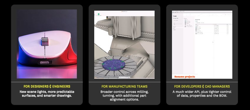
The September update is a big one for Fusion, and our last major product update before Autodesk University. This release brings faster performance, more predictable modeling, expanded sheet metal and manufacturing workflows, new PMI capabilities, greater control over product data, and plenty more across electronics, simulation, Render, and the API.
Whether you’re designing, programming toolpaths, managing product data, or putting the finishing touches on a render, there’s something new to explore. So grab your beverage of choice, settle in, and let’s dive in.
Key Highlights
- New Scene Lights in Render add configurable Point, Spot, and Photometric lights, providing greater control over lighting and product visualization directly in the Render workspace.
- Expanded Sheet Metal Workflows add Join by Bend, dedicated Sheet Metal Fillet and Chamfer tools, and Corner Closure Overlap to support more fabrication-focused workflows.
- More Predictable Lofting introduces deterministic mapping for supported closed profiles with matching corners, helping reduce unexpected twisting and misalignment.
- Performance Improvements make everyday work more responsive, with faster opening and closing of large designs, Window Selection, Section Analysis, and configured assembly workflows.
- Manufacturing Enhancements add greater control across machining and additive workflows, including improved Polar Machining setup, 2 Axis Part Alignment, broader Slice Analysis support, and more flexible additive arrangement tools.
- Electronics Enhancements expand schematic and PCB workflows with module bus authoring, plated through holes, improved component metadata, and schematic autorouting.
- Expanded Simulation and API Capabilities bring Modern Results to Modal Frequencies and Structural Buckling studies while extending automation across modeling, Drawings, and process simulation.
Usability
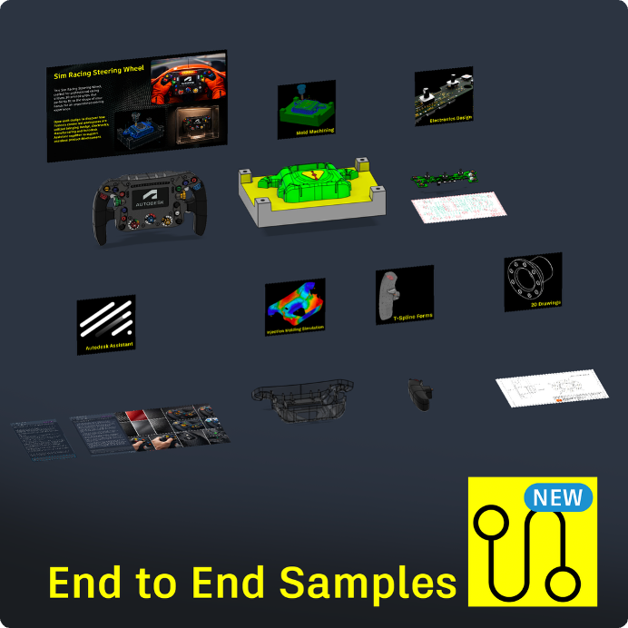
New in Fusion Samples: End-to-End Workflows
A new end-to-end sample project makes it easier to explore how Fusion connects design, engineering, and manufacturing workflows in a single project. Available directly from Fusion Home and the Data Panel, the first sample follows a Sim Racing Steering Wheel through mechanical assemblies, Form modeling, Electronics, Injection Molding Simulation, manufacturing toolpaths, 2D Drawings, and Autodesk Assistant.
By exploring the project from start to finish, you can see how multidisciplinary workflows connect across Fusion and apply similar approaches to your own product development process.
Orbit for Windows Touchpad
Windows users can now orbit the Fusion canvas using Shift plus a two-finger touchpad swipe. The gesture provides direct camera control without inertia and requires the use of gesture-based view navigation to be enabled in Preferences.
Note: This is the first iteration of Windows touchpad orbit support. We’re continuing to refine the experience and welcome your feedback as we make improvements in future releases.
Metal Graphics on macOS
Fusion now uses Metal as the default graphics driver on macOS. Metal is a more modern graphics foundation on Mac, designed to improve performance, responsiveness, and long-term compatibility with Apple hardware. Apple deprecated OpenGL on macOS but it is still available in the User Preferences if you need to return to the previously selected graphics driver.
Performance
As part of our ongoing work to improve Fusion performance and responsiveness, this release delivers targeted performance enhancements across key workflows. The highlights below represent measured improvements on large, complex datasets.
File Operations
- Open: Up to 30% faster first-time opening of large design files.
- Close: Up to 30% faster closing of large design files.
Window Selection
- Select All: Up to 55% faster on large design files.
- Extrude: Up to 6× faster when using Window Selection within the command.
- Sweep: Up to 3× faster when using Window Selection within the command.
- Revolve: Up to 75× faster when using Window Selection within the command.
- Arrange: Up to 3× faster after preselecting geometry with Window Selection.
- Hole: Up to 30% faster after preselecting geometry with Window Selection.
- Decal: Up to 28x faster after preselecting geometry with Window Selection.
- Assembly Constraint: Reduced from 5 minutes to under 2 seconds after preselecting geometry with Window Selection.
Section Analysis
- Graphics Interaction: Up to 2.5× faster when navigating designs with Section Analysis enabled.
Configurations
- Assembly Updates: Up to 80% faster for assemblies containing configurations.
- Insert Configurations: Up to 66% faster on the second and subsequent inserts from a configured design.
Note: These improvements are observed using datasets provided by our customers, and the performance gains can vary depending on the specific dataset.
Data Management
This release expands Fusion’s data management and collaboration capabilities, with improvements to shared-file workflows, BOM management, custom properties, Home, and Autodesk Assistant.
Learn more about Collaborative Editing (CE).
Clearer Collaboration
Improved Presence and Reservation Visibility
We’ve updated presence and reservation indicators across shared files to provide clearer and more consistent collaboration visibility. This release includes more accurate collaborator counts for open documents, visibility of your own presence in document tabs, and more consistent presence behavior when collaborators have multiple referenced files open.
We’ve also improved the usability of expanded presence lists and made it easier to distinguish between active presence and file reservations in design and assembly workflows. In addition, reservations are now released more quickly after Save completes, helping to reduce delays between edits. We’ll continue improving presence and reservation experiences in future releases, with ongoing work focused on clarity, consistency, and responsiveness across shared file workflows.
More control over your product data
Physical property override in Fusion BOM
You can now adjust calculated values like mass, volume, and dimensions directly in the BOM to reflect real-world conditions without modifying geometry or creating new file versions. Overridden values automatically feed into assembly rollup calculations and totals and are consistently reflected across all BOM views, exports, and APIs, giving your downstream teams and systems authoritative product data they can trust.
Learn more about how to override quantities and physical properties in Work with properties in the Bill of Materials.
Remove a reference component from specific BOM
The new Remove from This Parent option lets you exclude reference or construction-geometry components like skeleton models or mounting context parts from a specific assembly’s BOM without altering your design or affecting the same component in other assemblies.
Learn more about Remove from this parent.
Such excluded components and all their children are also automatically excluded from quantity rollups, physical property calculations, and exports, ensuring your BOM accurately reflects only what you build, buy, or ship. Every change is fully auditable and reversible, so you stay in control of your product structure with complete traceability.
Reorder component rows in Fusion BOM
You can now reorder BOM rows to match your team’s preferred component grouping, such as clustering hardware or electronics. This helps your BOM reflect how you actually organize and reference components. Changes persist across sessions and are consistently reflected in exports, APIs, and downstream consumers, ensuring everyone works from the same stable, engineer-defined ordering.
Learn how to reorder Bill of Materials rows.
Expanded custom property field types (Fusion Manage)
Fusion Manage now supports single-select picklists and checkboxes for custom properties, in addition to existing text, number, currency, and date fields. Picklists let you choose one value from a predefined set of options, while checkboxes support simple yes-or-no states. These additional field types give teams more flexibility to define properties that reflect their business processes and product data.
Enhanced Navigation Experiences
Home Improvements: History Panel, Project Renaming, Add to Assembly
Fusion’s Home experience now includes more of the data-management capabilities commonly used in the Data Panel, making it easier to manage and reuse design data from one place. You can now access design history and open previous iterations directly from Home. Projects can also be renamed without switching to the Data Panel or Fusion web. The Add to Assembly command is now available from Home, allowing you to find a design and add it directly to your desired assembly. Together, these additions reduce workflow interruptions and provide more direct access to common design-data actions.
Better folder security
We optimized folder security so that new folders are visible only to people who have permission to access them. This gives cleaner navigation with no change to what a user can open and access.
Autodesk Assistant
Autodesk Assistant is leaving Tech Preview in Fusion. This milestone marks its transition into a generally available Fusion experience. Those of you who previously opted out of the Tech Preview will now also have access to Autodesk Assistant as part of the Fusion experience.
Alongside this transition, Autodesk Assistant is expanding its data management capabilities with natural-language bulk updates.
Bulk property editing of components using Autodesk Assistant
Autodesk Assistant now accelerates repetitive data workflows by helping you find components in your hub, review their properties, and apply bulk property updates in a single prompt. For example, you can ask Autodesk Assistant to “Find all components with ‘Bolt’ in part name and set Vendor to ‘Arrow’,” to standardize properties across multiple components more quickly. This reduces tedious manual edits and accelerates downstream workflows like finalizing your BOM for release by letting you update many components at once instead of opening and changing properties one by one.
Custom property management via Autodesk Assistant (Fusion Manage)
Customers can now manage custom properties directly through natural-language conversations with the Autodesk Assistant, no need to navigate admin screens manually. This includes support for:
- Creating, updating, and deleting custom properties
- Setting property values on components
- Localization of custom properties
- Support for all data types, including the recently released single-select picklists and checkboxes
This makes custom property administration faster and more conversational for teams using Fusion with Fusion Manage.
HSCP Administration via Autodesk Assistant
You can now manage Custom Properties (HSCP) directly through natural-language conversations with the Autodesk Assistant — no need to navigate admin screens manually. This includes support for:
- Creating, updating, and deleting custom property definitions
- Setting property values on components
- Localization of custom properties
- Support for all data types, including the recently released single-select picklists and checkboxes
This makes HSCP administration faster and more conversational for teams using Fusion with Fusion Manage.
In-product purchase support with Autodesk Assistant
Autodesk Assistant can now help you understand your current subscription, extensions, licensing, product access, and purchase options without leaving Fusion. You can ask questions about what you already have access to or how to purchase additional subscriptions, extensions, or Flex tokens. When you’re ready to buy, Autodesk Assistant can open the in-product Purchase Manager with your confirmation, making it easier to move from exploring your options to making a purchase.
Moving to Collaborative Editing? Here’s what to expect
Collaborative Editing rollout
We are rolling out Collaborative Editing progressively across Fusion hubs. Before your hub transitions, admins will receive an email and all users will see an in-product notification with the rollout date. Once the update is complete, everyone will need to restart Fusion to access the new experience.
What you get with Collaborative Editing
- Editable Bill of Materials and Properties. Edit properties directly in the BOM or Properties panel. Changes are saved to the cloud, visible to teammates in real time, and tracked in design history.
- Shared part numbers. Manage multiple model variations under one shared part number to keep your BOM and property data aligned across the team.
- Versioning and history. Granular design history now tracks property and BOM changes alongside your save history.
- And more. Collaborative Editing also unlocks extended property search in Home, Autodesk Assistant, and Custom Properties.
Want to learn more about Collaborative Editing? Check out:
- The new Fusion Collaborative Data experience
- Collaborative editing
- Get answers to the questions your team will ask
Design
Environmental Mapping in Design
You can now evaluate surface quality and curvature continuity directly in the Design workspace with the new Environmental Map Analysis command. Real-time environmental reflections provide visual feedback as you model, helping you evaluate surfaces without leaving the Design workspace.
Environmental mapping can remain active as you iterate on your design, allowing you to continuously evaluate surface changes. You can also create and edit Environmental Map Analysis nodes for different analysis scenarios and adjust the reflection to support your surface evaluation workflow.
To get started, open Inspect > Environmental Map Analysis and select the geometry you want to evaluate. Use the live reflection visualization to assess surface quality and curvature continuity as you continue working on your design.
As part of this update, the Inspect menu has also been reorganized with improved grouping to make tools easier to navigate.
Learn how to analyze surface reflections with environment map
On-Canvas Names for Construction and Origin Planes
Construction and origin plane names can now appear directly on the canvas, making it easier to identify the right reference plane in designs with multiple planes without repeatedly checking the browser.
Labels use the plane name shown in the browser and Timeline and update automatically when a plane is renamed. Plane names are positioned at the upper-left of each plane, orient with the plane, and adapt to the active visual environment.
New Object Visibility controls for Construction Plane Names and Origin Plane Names let you show or hide these labels independently from the plane geometry. This means you can display plane names when you need additional context or hide them for a cleaner canvas without changing the visibility of the planes themselves.
To control the labels, open Object Visibility and toggle Construction Plane Names or Origin Plane Names on or off. Rename a plane in the browser or through Edit Feature and the on-canvas label updates to match.
Learn how to show or hide plane names on canvas.
Enhanced Plane Along Path
Plane Along Path now supports construction axes as path inputs and adds more options for controlling where a construction plane is placed. In addition to Proportional and Absolute placement, the new To Object extent lets you position a plane relative to an existing reference, with an optional Offset.
You can select origin axes and construction axes created with other Construct commands as the path. When using To Object, supported reference geometry includes vertices, work points, and sketch points, helping you position the plane relative to existing design geometry without creating additional helper geometry.
To use the enhanced workflow, choose Construct > Plane Along Path, select your path, and choose an Extent Type:
- Proportional — Position the plane proportionally along the selected path.
- Absolute — Position the plane using an absolute distance.
- To Object — Position the plane relative to a selected reference object, with an optional Offset.
Plane Along Path settings remain editable through Edit Feature and persist through save/reload and Timeline recompute.
Learn how to create a plane along path.
Predictable Lofts for Closed Profiles
Loft now uses a deterministic mapping method for supported closed profiles with matching corners, providing more predictable results when working with rotated or shifted sections. Fusion automatically detects section orientation and consistently maps matching corners between profiles, helping reduce unexpected twisting and misalignment.
There’s no change to the existing Loft workflow. Create your closed profile sections and use Loft as usual; when the profiles are supported, the new mapping behavior is applied automatically.
The new behavior applies to closed sections with matching numbers of clearly defined corners. Loft cases outside this scope continue to use the existing behavior.
Learn more about loft references.
More Reliable Boolean Operations
Fusion can now automatically apply a mesh-assisted fallback when Unite, Intersect, or Subtract would otherwise fail on complex or near-coincident geometry. This helps recover operations that previously failed, including challenging cases involving imported CAD and complex solids, without changing the existing Boolean workflow.
The fallback uses Autodesk Rational Mesh Boolean (ARMB) technology. When Fusion encounters geometry that cannot be resolved by the standard Boolean operation, the mesh-assisted method is applied automatically in the background. Testing showed that it recovered more than 60% of previously failing Boolean operations and was 15× faster than the previous mesh Boolean technology.
There’s nothing new to configure or learn. Continue using Unite, Intersect, and Subtract as usual, and Fusion handles the fallback automatically when needed.
Finish Sketch with AutoConstrain
Finish with AutoConstrain is a new option in the Finish Sketch menu that automatically applies sketch constraints when you finish a sketch. Fusion runs AutoConstrain in the background after the sketch is closed, helping you create more robust, fully constrained sketches without disrupting your existing workflow. See Finish with AutoConstrain
Create Product Manufacturing Information (Manufacturing Extension or Design Extension)
You can now create and edit Product Manufacturing Information (PMI) directly in the Design workspace using two new commands on the Utilities tab: Hole/Thread Note and Leader Note.
- Hole/Thread Note lets you select a hole or boss and add information such as diameter, depth, tolerances, threads, and counterbore or countersink dimensions, with annotations that support ASME or ISO standards. PMI can be applied to a single hole or boss, or to identical features found by the command. PMI settings, including standards and text size, are available under Document Settings in the Browser.
- Leader Note lets you associate text with a surface, edge, or point.
PMI can be used across parametric and direct modeling workflows and consumed downstream in the Manufacturing workspace, including hole machining and inspection workflows. Imported PMI can also be converted to native Fusion PMI for editing, while both imported and native PMI can be used in Manufacturing.
Configurations
BOM support for Configured Designs
The BOM (Bill of Materials) command is now supported for Configured Designs. The BOM automatically reflects the active configuration, so you can validate product structure and communicate accurate information downstream.
- Open or create a Configured Design
- Open Bill of Materials from the toolbar to see the BOM for the current active configuration
- Activate another configuration to automatically refresh the BOM; no extra steps needed
Configure Group Feature Suppression
Configured Designs now support suppression of Group features, making it easier to control grouped design variations across configurations. When a Group feature is suppressed for a configuration, all features within that group are suppressed together. Unsuppressing the Group feature restores all features within the group.
To configure Group Feature Suppression, right-click a Group feature in the Timeline and select Configure. Select Suppression to add a suppression column for the Group feature to the Configuration Table. You can then suppress or unsuppress the entire group for each configuration row.
Learn more about configuring suppression states
Number lists in Configuration Rules (Design Extension)
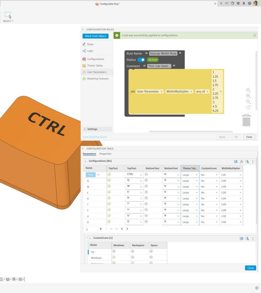
Configuration Rules now lets you define a list of specific allowed numbers for a numeric parameter. Instead of creating a Theme Table to restrict a parameter to a set of discrete values, number lists give you precise control over exactly which values are valid in a configuration.
- In the Design workspace, open Configure > Create Configuration Rules
- In any Getter or Setter block, expand the operator list and select the new Any Of option.
- Add each allowed value to the number list (for example, 5, 10, or 20 mm)
- In the Getter block, you can also select the None Of operator to create an explicit list of disallowed numeric values.
Learn more about Configuration Rules
Sheet Metal
Join by Bend
The new Join by Bend tool makes it easier to connect separate Sheet Metal bodies when they can be joined with a single bend. Instead of manually remodeling the parts to connect them, Fusion creates the bend between the two bodies directly within the Sheet Metal workflow.
Join by Bend uses the active Sheet Metal rule to apply the bend parameters and supports a bend radius override when a different value is needed.
To get started, open the Sheet Metal workspace and use Join by Bend from the Sheet Metal tab to select the bodies you want to connect.
Learn how to Join by Bend.
New Sheet Metal Fillet and Sheet Metal Chamfer tools
New dedicated Sheet Metal Fillet and Sheet Metal Chamfer tools are now available in the Sheet Metal tab, providing edge-treatment tools designed specifically for sheet metal fabrication workflows.
The new tools restrict selection to valid sheet metal edges, such as edges perpendicular to the flat pattern (“Z-up” edges). This helps prevent the selection of long formed edges that are not manufacturable using standard sheet metal processes and makes it easier to target smaller edges and corners when preparing parts for manufacturing.
For edge treatments outside of these sheet metal-specific workflows, the standard Fillet and Chamfer tools remain available from the Solid tab.
Learn more about Sheet Metal Fillet and Sheet Metal Chamfer.
New Corner Closure Overlap
The Corner Closure tool in the Sheet Metal workspace now supports overlap corner conditions in addition to the existing symmetric gap behavior. This gives you more control over how adjacent flanges meet and helps support fabrication and assembly workflows that require overlapping corners.
A new slider lets you adjust the overlap from 0 to 1. At 0, the flanges meet without intersecting; at 1, one flange fully overlaps the other. You can also use Flip Overlap to switch which flange drives the overlap condition.
These controls make it possible to create overlap conditions directly within Corner Closure, reducing the need to manually model these corner treatments.
Learn more about Corner Closures.
Mesh
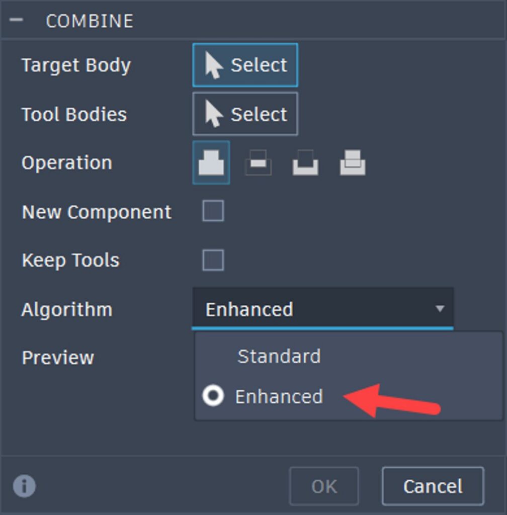
New Mesh Boolean Algorithm
A new algorithm called “Enhanced” has been added to the Combine command in the Mesh workspace. This uses a new multi-threaded approach that produces meshes with fewer triangles than the standard option.
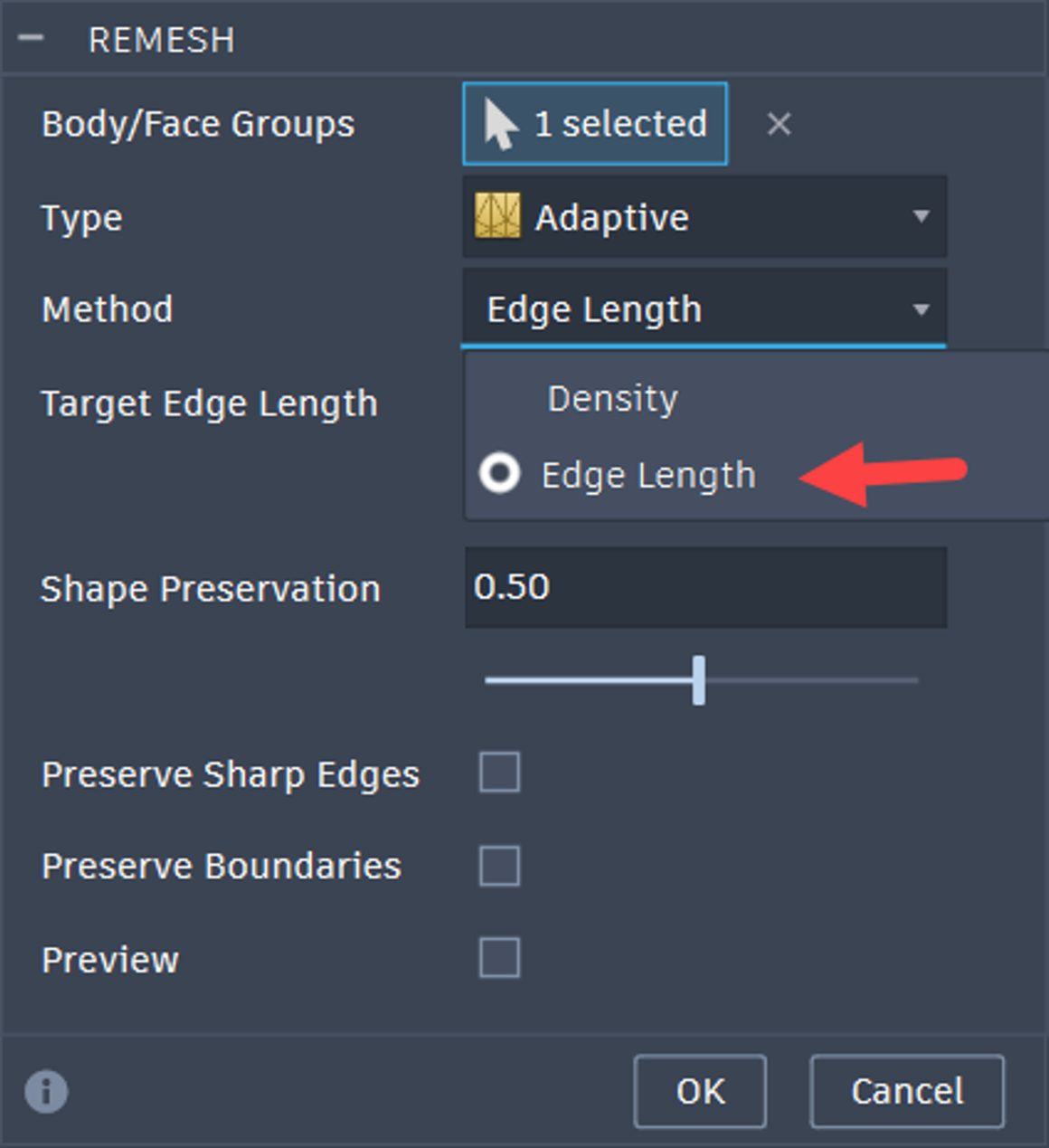
New Method for Remeshing
You can now remesh based on Edge Length in addition to the existing Density option, allowing you to specify a Target Edge Length that controls the remeshing result. The option is available for both Adaptive and Uniform remeshing.
Drawings
Robust Dimension Associativity
In Drawings, dimensions and annotations now remain associative through common model changes that previously could cause them to become disassociated. This helps preserve annotation references as designs evolve, reducing the need to recreate dimensions and hole notes after changes.
This improvement applies to the following workflows:
- Delete Body or Component — When a body or component is deleted, associated dimensions and annotations update automatically. Annotations that no longer have a valid reference are removed from the drawing.
- Change Hole Type — Dimensions and hole notes remain associated when the hole type is modified, whenever possible, reducing the need to recreate them manually.
- Hide or Show Body/Component — When a body or component is hidden, its associated dimensions and annotations are hidden as well. When the geometry is shown again, they are restored and re-associated wherever possible.
- Suppress or Unsuppress Body/Component — Dimensions and annotations respond to suppression changes by hiding and restoring with their associated geometry while maintaining associativity wherever possible.
Together, these improvements help reduce drawing cleanup and preserve dimensions and annotations as the model changes.
Note: ACM Symbols are not supported for these workflows.
Support Leader Note on Sketch in Drawings
You can now attach Leader Notes to sketch geometry in Drawings. Leader Notes are supported for both Sheet Sketches and View Sketches, making it easier to annotate and document sketch geometry directly within your drawings.
Improved Zoom Experience
Zooming in Drawings now centers on the cursor position, making it easier to navigate and inspect detailed areas of a drawing. The updated behavior reduces unnecessary panning and provides a navigation experience that is consistent with the Design workspace on macOS.
Render
Scene Lights in the Render Workspace
Fusion now lets you add and place your own light sources in the Render workspace, giving you direct control over illumination and highlights, and where light and shadows fall in your renders.
Previously, render lighting came from environment lighting alone. Now you can add discrete lights and position them anywhere in your scene, so you decide exactly where light and shadow fall — brighter product highlights, deliberate shadows, and physically accurate results that match real-world fixtures. It’s a meaningful step toward art-directing your renders the way a photographer or lighting artist would.
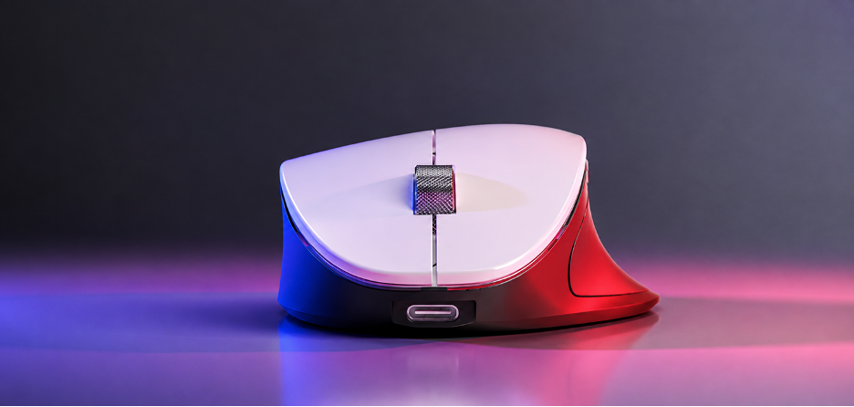
To use the feature, open the Render workspace and select Lights on the toolbar. You can add up to eight lights per design and choose from three types:
- Point lights radiate in all directions and are ideal for bulbs and fill lighting.
- Spot lights use a cone-shaped beam for accents and product highlights.
- Photometric lights use real-world lighting data for physically accurate results.
Position and aim each light directly in the canvas using Modify Position and Modify Direction, then adjust its intensity, color, and temperature. Spot lights include Hotspot and Falloff controls to shape the beam. Photometric lights support standard lighting units, including lumens, lux, and candelas, along with IES distribution profiles. You can also combine Scene Lights with environment lighting in Scene Settings.
Key things to know:
- A maximum of eight lights can be created per design. Delete an existing light to add another.
- After placing a light, you can’t change its type. To use a different light type, delete the existing light and place a new one.
Learn more about adding scene lighting in your render.
Electronics
Bus Authoring for Modules
We’ve expanded schematic bus authoring to support buses inside modules and expose them cleanly at the top level through bus ports. Complex buses including multi-member, ranged, and aliased definitions, can now be exported from a module as a single port, with the port name matching the internal bus specification by default. At the top-level sheet, module bus ports can connect to schematic buses even when member names, aliases, range indices, or sort order differ, as long as the overall bus structure matches. This makes hierarchical bus connectivity more flexible while preserving correct net recognition.
To support this, each bus port instance now maintains its own internal-to-external net mapping, which users can review and reorder in the Inspector. New Inspector rows show the connected bus and the active bus mapping, while updated visual indicators on the port tip make compatibility state easier to understand at a glance. We’ve also added a new schematic-only PORTMAP CLI command for scripting or manually reordering mappings. Mapping data is persisted per port instance in the design file, ensuring that hierarchical bus connections remain stable and portable across sessions.
Plated Through Holes (PTH) in 2D and 3D PCB
Fusion Electronics now supports Plated Through Holes (PTHs) in both 2D and 3D PCB workflows, providing greater control over PTH geometry and synchronization between PCB environments.
You now have more control over PTH creation and management, including:
- Multiple pad shapes: The new PTH command in the 2D PCB workspace supports circular, rectangular, hexagonal, and slotted pad shapes. Pad dimensions can be defined manually or calculated automatically from the hole diameter.
- Solder mask controls: Configure solder mask behavior using automatic generation, a custom offset, or complete removal.
- 2D-to-3D PCB support: When a design is pushed to the 3D PCB workspace, Fusion creates the corresponding copper pads and plated hole or slot geometry. PTH dimensions and positions can then be edited directly from the 3D PCB Timeline.
- Synchronized changes: Update 2D PCB keeps PTH changes synchronized between the 2D and 3D PCB workspaces. Synchronization can also be deferred, with updates applied later through the standard push-and-pull workflow.
- Organized 3D PCB geometry: PTH copper pads and holes are organized under the top and bottom copper nodes in the 3D PCB browser, making them easier to locate and manage.
Together, these improvements provide finer control over PTH design and synchronization across 2D and 3D PCB workflows.
Component categories and suggested attributes
Electronics components now include Category attributes that let you identify the category a component belongs to. Once you select a component category, Fusion suggests relevant attributes that can be added based on the selected category.
This provides a more guided workflow for defining component metadata and can help teams create more complete and consistent component information across libraries and designs.
Updated Variant Panel in the Library Workspace
Creating and editing variants in the Library workspace now uses the unified right-side panel layout. The Variant panel is grouped with the other panels on the right side of the workspace, providing a more consistent interface when working with library content.
NETROUTE for Schematic Autorouting
Fusion Electronics introduces NETROUTE, a new schematic autorouting command designed to automatically connect multiple pins for scripting, automation, and AI-driven workflows.
NETROUTE accepts two or more pin targets in a single call and routes them on the current schematic sheet while avoiding symbol bounds, existing pins, and unnecessary net crossings. When appropriate, it can also introduce intermediate connection points to create a shorter or cleaner route.
For unattended workflows, the optional NOCONFIRM mode suppresses power-net confirmation prompts, making NETROUTE better suited for automated scripts and test flows.
NETROUTE is designed primarily for scripting, automation, and AI-driven schematic generation rather than changing the standard interactive schematic routing workflow.
Simulation
New Simulation Results Experience for Modal Frequencies and Structural Buckling (Simulation Extension)
We are continuing to modernize the Simulation post-processing experience. The modern Simulation Results experience is now available for Modal Frequencies and Structural Buckling studies, expanding support beyond Linear Static Stress, Thermal, and Thermal Stress.
Modal Frequencies and Structural Buckling studies now use the same modern post-processing workflows for result visualization, animation, cutting planes, compare, and reporting as the other supported study types.
If you encounter any issues, you can switch back to the classic results experience by navigating to Account > Preferences > Preview Features > Simulation.
Learn more about the new Modal Frequencies and Structural Buckling results viewing experience.
Manufacturing
New 2 Axis Part Alignment (Manufacturing Extension)
Part Alignment now includes a new 2 Axis method for setting more accurate work offsets on rotationally symmetric parts where the center of rotation is already fixed by fixturing. The method corrects rotational timing around the fixed center point and can optionally translate along the axis of rotation to help balance measured deviations. This makes it well suited for parts such as propellers, impellers, and other highly rotationally symmetric components.
Learn more about part alignment using probing.
Asymmetric Size Tolerances for Probing
After being available in Fusion Insider Preview since April, Asymmetric Size Tolerances for Probing is now generally available. Probe WCS and Probe Geometry now support independent upper and lower size tolerances, allowing probing workflows to more accurately reflect asymmetric and unilateral tolerance requirements, including cases where one tolerance is zero or both values are positive or negative.
For probing cycles that accept only a single symmetrical tolerance value, Fusion automatically adjusts the nominal size and tolerance sent to the CNC controller while evaluating the feature against the intended tolerance range. As a result, values in the NC program may differ from those displayed in Fusion, while the feature is still evaluated correctly.
The enhancement also connects with Fusion’s new PMI authoring capabilities. Probing operations can inherit relevant asymmetric tolerances from PMI Hole/Thread Notes, reducing the need to manually re-enter inspection requirements.
Learn more about asymmetric size tolerances for probing.
Want earlier access to capabilities like this? Join the Fusion Insider program to explore upcoming functionality, try new workflows before general availability, and share feedback that helps shape future Fusion releases.
Create Milling Tool Holder from Solid Model
You can now create a milling tool holder directly from imported solid geometry, such as a STEP model provided by a manufacturer. Fusion converts the selected 3D geometry into the holder’s 2D spun profile, reducing the need to manually recreate the holder profile.
The new holder is added to the current document, where you can copy it to a library and assign it to tools.
When creating the holder, you can define the gauge length from the solid geometry, with options to offset from a reference selection or from the top or bottom of the selected solid. This provides flexibility for working with different manufacturer gauge length definitions.
The resulting holder profile is a spun 2D profile derived from the selected solid geometry.
Easier Polar Machining Setup
Polar machining options are now available directly in the Toolpath Operations dialog, making it easier to access and configure polar machining within your existing workflow. Selected strategies also now support optimized polar links.
For 3-axis toolpaths in a mill/turn setup, new options provide more control over rotational moves and can help keep the toolpath within the machine’s travel limits. You can allow a pre-toolpath rotational move or, when required, enable polar machining for the full toolpath.
This gives you more flexibility when programming toolpaths that use polar machining while keeping the setup within the Toolpath Operations workflow.
Trimmed Drilling Collision Avoidance
A new Trimmed option is now available in the Shaft and Holder Mode dropdown for Drilling operations. When Fusion detects a collision on a cutting move, it retains the safe portion of the move and trims away the colliding portion rather than removing the entire move.
Trimmed can be used with Remaining holes from Operation in the Selection Mode dropdown on the Geometry tab. For example, an initial drilling operation can use a shorter, more stable tool to machine as much of the selected holes as it can without collision. A subsequent operation can select the remaining holes from the first operation and use a longer tool to reach areas the shorter tool could not.
Multiple drilling operations can be chained in this way, allowing progressively longer tools to complete holes that shorter tools cannot fully reach.
Learn more about Drilling.
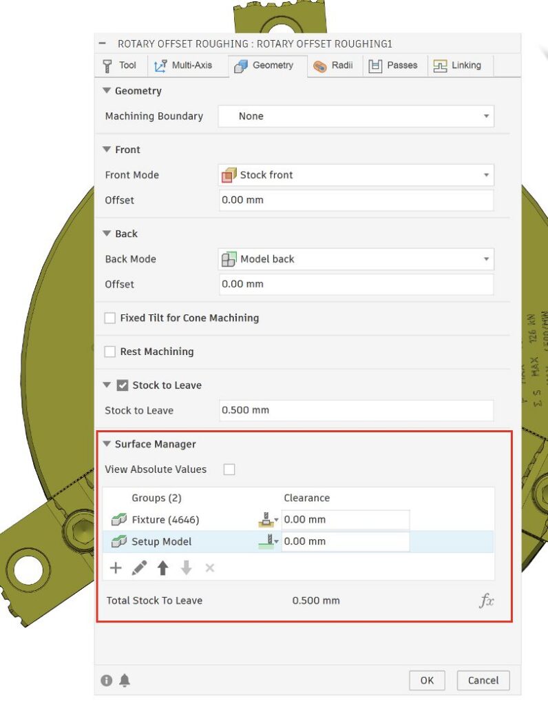
Surface Manager for Rotary Offset Roughing and Rotary Contour (Manufacturing Extension)
The Surface Manager table on the Geometry tab is now available for Rotary Offset Roughing and Rotary Contour, giving you more control over which surfaces these strategies machine or avoid.
Fixture surfaces already defined in the setup are automatically included as surfaces to avoid. You can also select additional surfaces to machine or avoid as needed.
This helps account for fixture surfaces directly within these rotary strategies while providing additional control over the surfaces included in the toolpath.
Learn more about Rotary Pocket Steps and Multi-Axis Rotary Contour steps.
Toolpath Update Notifications
A new notification bell is now available at the bottom of the 3D toolpath form to help you stay aware of important changes that may affect your toolpath workflows.
When new information is available, an orange dot appears on the notification bell. Select the bell to open a web page with details about changes that may affect existing toolpaths when they are recalculated, as well as updates to the toolpath form workflow that may require your attention.
After you open the notification, the orange dot disappears to indicate that the information has been viewed.
Deburr Point Stripping (Manufacturing Extension)
The Deburr toolpath strategy now automatically removes redundant points from cutting passes, reducing unnecessary point data while maintaining the intended cutting path.
This produces more efficient Deburr toolpaths without requiring any changes to your existing workflow.
Learn more about Deburr.
Additive Manufacturing
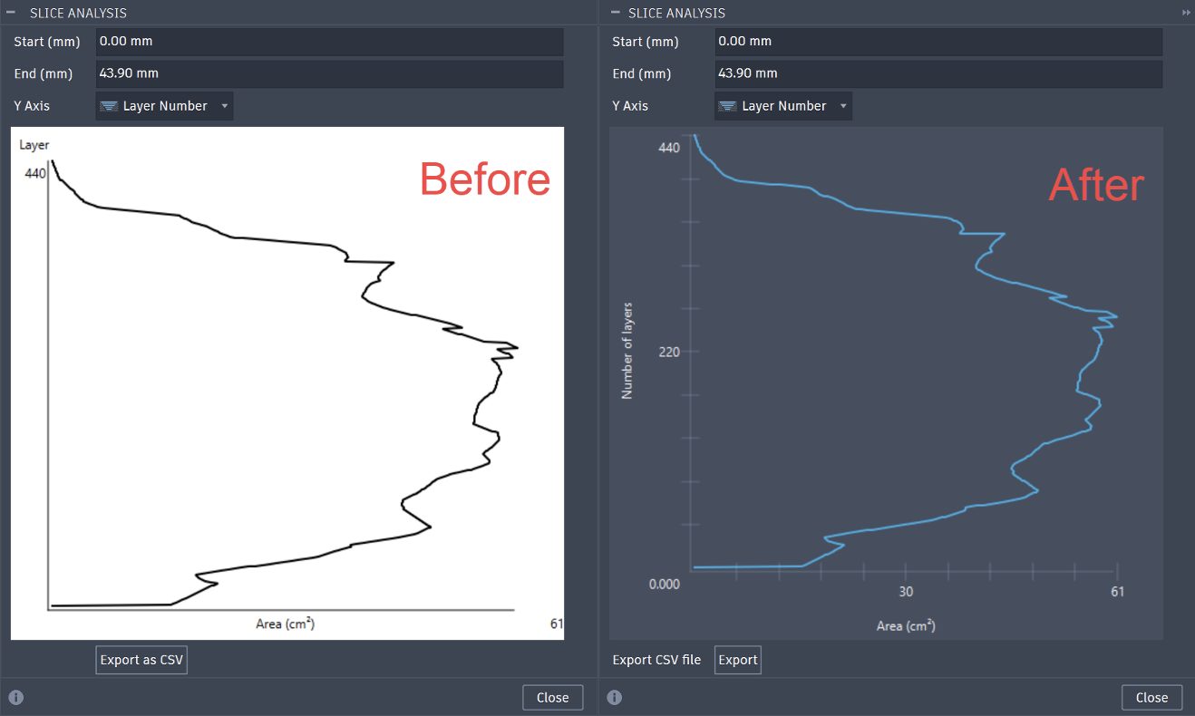
Improved Slice Analysis
Building on the July release of Slice Analysis, we’ve improved the dialog experience and expanded support across all Additive technologies. Previously available for SLS, MJF, and MPBF, Slice Analysis can now be used across the full range of Additive workflows in Fusion.
Learn how to analyze slice statistics.
Manually group components before arranging
You are now able to manually define a Sub-Nest group by using the Sub-Nest command but deselecting the Arrange Components checkbox, giving you more control over arrangements for 3D nesting workflows.
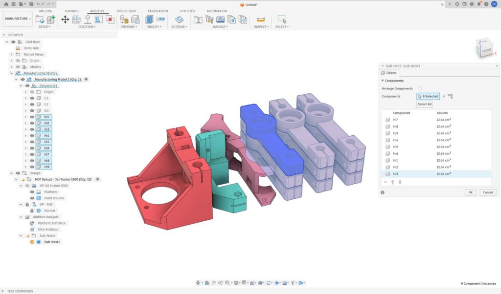
Learn how to arrange a sub-nest for additive manufacturing.
Monte Carlo arrangement type is no longer available
The Monte Carlo arrangement type has been removed as an option in the Additive Arrange dialog. Users will now only be able to select between the 2D Packing (True Shape) and 3D Packing (True Shape). True Shape is our best-in-class nester. The True Shape arrangement type has the following features that the Monte Carlo arrangement type did not include:
- Supports no-build zones and locked parts
- Can rotate parts during packing
- Can duplicate parts during packing
- Generates repeatable outcomes
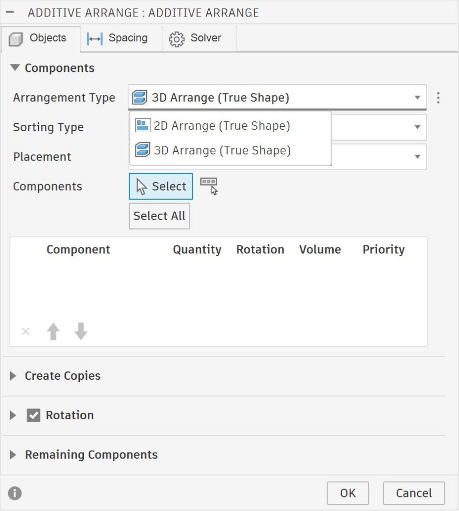
Learn more about arrangement for Additive Manufacturing.
Full machine visibility controls
You are now able to control the visibility of the platform, build volume, and no build zones individually. Furthermore, we have split the no build zones into separate nodes allowing the user to also individually control their visibility.
API
There’s a lot new for developers in September. This release expands automation across modeling, Drawings, and process simulation, alongside the full release of TypeScript support for Fusion scripts and add-ins.
Expand below to explore the latest additions to the Fusion API.
Expanded Modeling API Capabilities
The Fusion API now supports additional modeling and construction geometry workflows, helping developers automate tasks that previously required more manual interaction.
New capabilities include:
- Construction Plane on Path with Absolute Distance — Create construction planes at a specified absolute distance along a path.
- Point on Path — Programmatically create points at specified locations along a path.
- Timeline and TimelineObject Attributes — Access expanded timeline attributes to support more control over design history and sequencing.
- Centre Point Arc Slot — Create center point arc slots programmatically for additional sketch automation workflows.
Together, these additions expand the modeling workflows available through the Fusion API and provide more options for building automated and repeatable design processes.
Expanded Drawing API
The Drawing API now supports a broader range of drawing automation workflows. New capabilities include creating drawings with Manual workflow and Smart Templates, automating detailing with Tidy Up and Auto Dimension, managing sheet and document settings, working with drawing views, bend tables, images, and custom tables, and exporting drawings in DXF and DWG formats. Updated developer documentation for Drawing Creation and PDF Export APIs makes it easier to build and integrate automated drawing workflows.
MPBF Process Simulation API now available
The API for Metal Powderbed Process Simulation has migrated out of preview and now will be available for all those who want to use it. Users are now able to access and execute Process Simulation workflows programmatically, enabling automation, custom workflows, and integration with external tools and scripts. As part of this work, users are also able to display the results, which was previously not possible.
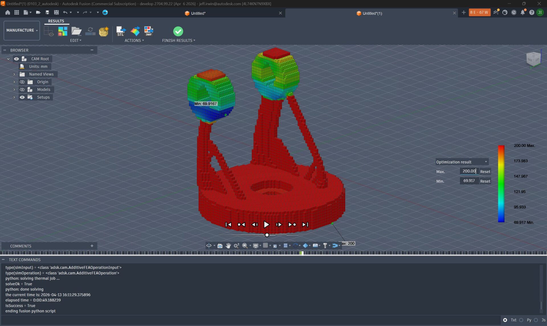
Please see the following help page sample script:
Additive MPBF FEA Process Simulation API Sample script
MPBF Process Simulation results via API now displayed
MPBF process simulation results are now displayed via the API. Previously the results were only displayed using the UI.
TypeScript API
TypeScript support in the Fusion API is now fully released. Developers can build scripts and add-ins using TypeScript alongside Python and C++, benefiting from strong typing, modern development tools, and the same debugging experience available across existing Fusion API workflows. TypeScript also streamlines Automation API development by enabling local development and debugging before submitting jobs. Scripts and add-ins continue to run in a sandboxed environment with configurable read and write permissions.
Release Notes
To see more fixes, minor enhancements, and keep up with the latest check out our Release Notes for more information on changes to Fusion and Fusion web client.
Fusion Insider
Do you want to engage more with the Autodesk community? Check out the Fusion Insider program to use exclusive previews, and test out the latest build before it’s released to the public.
As a member, you’ll gain inside knowledge of updates and a first look at new features. You’ll also be able to join exclusive events and try pre-release functionality. Plus, you can give feedback directly to the product teams.