Do you find yourself needing more flexibility in designing custom components that aren’t readily available? Or perhaps you need to know how something in your architectural design responds to heat or expected forces?
Then it’s time for you to unleash your architectural designs’ potential with Autodesk Fusion.
Creating detailed, complex and parametric models is the Fusion superpower. You can also run simulations of all flavors, render, animate, and manufacture your designs by just switching around the workspaces. It’s affordable and incredibly intuitive as we will demonstrate in this lab. Any type of fabrication drawings can be automatically created for fabrication including our array of sheet metal capabilities.
This will be a series of blogs detailing seven exercises that explore the powerful features of Fusion, with a key focus on detailing work. There are plenty of exercises and real-world examples to help contextualize the learning objectives. doesn’t matter if you’re a beginner or someone looking to refine— there is valuable information for every type of user. Get ready to upgrade your architectural prowess.
A Quick Overview of Exercise 1
Let’s begin with a layout that might look familiar to you– the early design of a residential structure.

This seemed like the perfect bridge between architectural datasets and Fusion capabilities. While Speaker typically creates stud layouts in Revit using curtain walls, I find Fusion suited for this task too.
The primary goal of this first exercise is to help you get acquainted with the Fusion interface. This model is exported the DXF of the foundation from Revit and recreated it in Fusion.
The Fusion Interface primarily contains the ribbon, modeling space, and the data panel that usually lives minimized.

The Feature Timeline at the bottom of the interface contains all the features needed to build this design. Fusion allows you to edit previous features or sketches easily or roll the history marker back to replay the modeling sequence. You can move the features around too or insert new ones. Pair the feature timeline with configurations and parameters and you can have an entire suite of engineering variations in one design.
Try modifying the timeline:
- Click the small “+” to expand groups
- RMB a feature and select Edit, then Cancel.
- Roll the history marker backwards and release to see the design at that stage
- Roll it back to the end before the next section
Exercise 1.1 – Introduction
Let’s get started adding the remaining studs required for this structure:
- Ensure that your sketches are all visible in the Browser Tree.
- In the Create ribbon dropdown select Pattern, then Pattern on a Path

- Select the body in the Fusion interface OR select the Pattern Stud body from the browser
- Select Path in the dialog
- Then select the Sketch of the sill plates that goes through our reference point
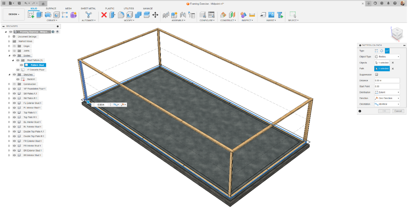
- Change the Distribution to Spacing
- Set Distance to 15.75”
- Set the quantity to your best guess.
Odds are you didn’t select the exact number of studs correctly, and most likely you aren’t aligned as expected around the perimeter of the structure.
Fusion uses parametric modelling, allowing us to jump back into commands we’ve executed and adjust them, configure them, and even reorder them. - RMB the pattern feature in the timeline
- Select Edit Pattern on Path
- Set Quantity to 102
- Set Orientation to Path Direction
Here are some takeaways from Exercise 1.1:
- The data panel is used to access all your designs in Fusion
- The History Marker is used to drag you current working place throughout the design’s history
- The options in dialogs are incredibly powerful and must be read carefully
- Browser objects, features, and groups of features can be renamed with RMB
- We can highlight objects in Fusion by dragging left to right to select only items we encompass and right to left to select anything the box touches.
- Selection Priority and Filters is found under Select on the ribbon
Exercise 1.2 – Adding an External Component
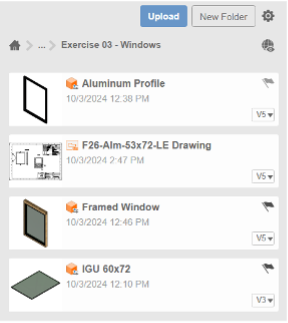
- Expand the data panel and navigate to Exercise 03 – Windows
- Select Framed Window and drag it into our design. (You can also RMB Insert into Current Design)
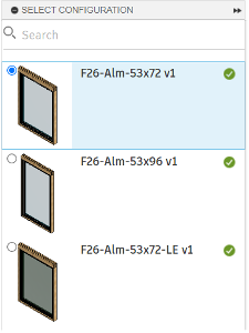
- You will then be prompted to Select Configuration.
- Select F26-Alm-53×72.
- Navigate up to the Assemble ribbon and select joint (Or press “J”)
- Zoom in via the scroll on your mouse and place a joint origin on the top left corner of the window
- (For simplicity, ensure the Joint Origin Z-Axis in blue points away from the component as pictured)
- TIP: Holding CTRL limits the placement of the joint origin on a surface, corner, or edge
- Pan to the Top-Left corner of the existing structure using MMB drag
- Select the corner of a 2×6 (once again with the Z-Axis pointing out
- Select “Flip” in the dialog if necessary to align
- Offset the X-Axis so the Window header is 10” from the top plate
Exercise 1.3 – Edit in Place
- Navigate up to Modify
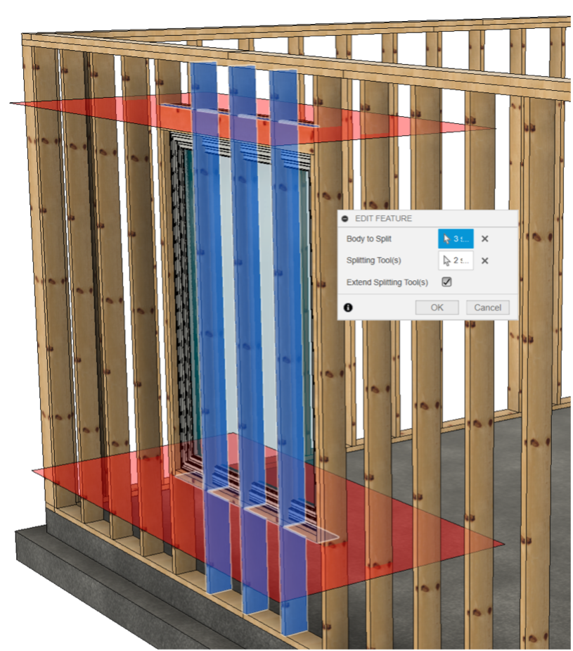
- Select Split Body
- For “Body to Split” select the three intersecting 2×6’s
- For Splitting Tool(s) select the top and bottom of the window rough in framing
- Click Extend Splitting Tool(s)
- Click OK
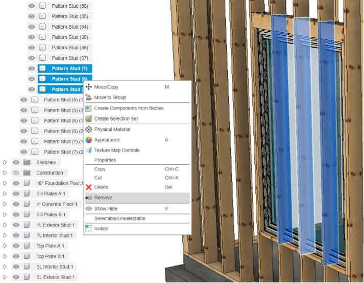
- Expand the Bodies Browser node
- Scroll down to the bottom of the list
- Find the three intersecting 2×6’s by hovering to highlight
- CTRL-LMB select all three intersecting bodies
- RMB and select Remove
Now that you’ve familiarized yourself with the Fusion interface, stay tuned for future exercises where you get to create custom components for your architectural designs!