 Annaka Ketterer

Fusion’s July update introduces a refreshed Home experience, Construction Geometry enhancements, Hub-Based Threads Library, Altium Project Import, new manufacturing capabilities, and more.
Minor Update
Our latest minor update brings several important fixes and improvements to enhance your experience. Click to learn more.
v.2704.1.53 – August 6, 2026
Usability
- Fixed a crash on macOS that could occur when accessibility features such as VoiceOver were enabled.
- Fixed an issue where the Fusion Service Utility could fail to open.
Data Management
- Fixed a crash that could occur when switching to online mode while working with configured designs.
- Fixed a crash that could occur when closing a referenced document while an external reference update was still in progress.
- Fixed a crash that could occur when opening certain assemblies.
Design
- Fixed a crash that could occur when using Get All Latest on assemblies containing inserted configurations.
- Improved performance when opening component context menus in large assemblies.
Manufacturing
- Fixed a crash that could occur when using GPU simulation.
v.2704.1.36 – July 19, 2026
Data Management
- Fixed a crash that could occur when opening documents with version history.
Design
- Fixed an issue where configured designs could fail to reflect updates to referenced components.
Sheet Metal
- Fixed an issue where the Sheet Metal Rules Library could intermittently fail to load.
Drawings
- Fixed an issue that could prevent users from switching to the Drawings workspace, resulting in a “Fusion Drawings cannot launch” error.
- Fixed a crash that could occur when opening or creating drawings.
Usability
- Fixed an issue where canvases could move in the wrong direction when using Edit Canvas.
- Fixed an issue where the previous My Fusion experience could briefly appear before the new Home experience loaded.
v.2704.1.23 – July 9, 2026
Data Management
- Fixed an issue where updates to Shared Part Numbers could fail to save.
Design
- Fixed an issue where configuration names did not display according to the selected preference.
Sheet Metal
- Restored the Sheet Metal Rule selector in the New Component dialog.
Electronics
- Fixed an issue where the BSDL Component Generator could fail to create a component when another design document was already open.
Manufacturing
- Fixed an issue where GPU simulation could fail to detect collisions between the tool and fixture.
- Improved Tool Library loading performance.
Stability
- Fixed a crash that could occur when closing Fusion or closing a document.
- Fixed a crash that could occur during application shutdown when using a SpaceMouse.
- Fixed a crash that could occur when launching Fusion.
Highlights
v.2704.1.15 – July 6, 2026
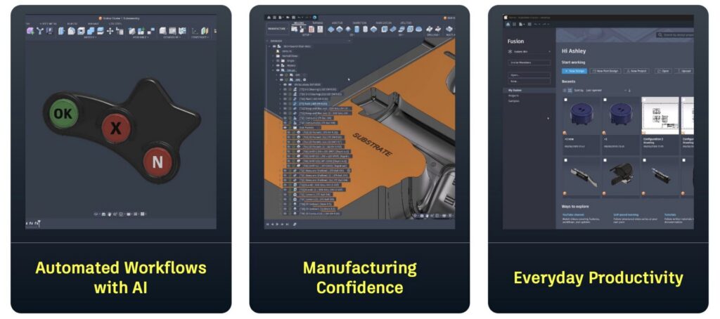
The July release of Autodesk Fusion introduces new capabilities across design, manufacturing, electronics, data management, and API development. This release focuses on helping teams work more efficiently, whether that means simplifying configurable product workflows, improving manufacturing toolpath strategies, streamlining electronics migration, or making it easier to manage and collaborate on design data.
Key Highlights
- A Refreshed Fusion Home Experience brings recent work, project management tools, search, Autodesk Assistant, and personalized resources together in a more connected starting point.
- Construction Geometry Enhancements add new capabilities for creating perpendicular planes on curved faces, resizing construction geometry, applying offsets during creation, and mirroring construction geometry.
- Hub-Based Threads Library provides a centralized way to create, manage, and share custom thread definitions across teams and projects.
- Altium Project Import helps teams migrate Altium Designer projects into Fusion Electronics while preserving key design information.
- 3+2 Clearing introduces a new toolpath strategy for removing stock from multiple fixed orientations within a single operation, helping reach areas that may otherwise be difficult to machine.
- Ramp: Machine Shallow Areas expands Ramp machining workflows by automatically adding additional stepdowns in shallow regions to improve toolpath coverage.
Performance and Productivity
As part of our ongoing work to improve Fusion performance and responsiveness, this release delivers targeted performance enhancements across several common workflows. The improvements below were measured using large, complex customer datasets and are designed to help reduce wait times across file operations, configurations, drawings, and common interaction workflows.
File Operations
- Close design files up to 4x faster
- Export STEP files from a Collaborative Editing Hub up to 30x faster
- Open imported STEP files up to 15% faster
Interaction & Productivity
- Select All operations up to 55% faster
- Deselect operations up to 15% faster
- Arrange execution up to 3x faster when arranging all components in a design
Faster Configurations
- Large configuration tables (100+ rows and columns) up to 10x faster
- Configuration activation up to 80% faster by avoiding re-computation of suppressed features
- Configuration insertion up to 12% faster
Improved Drawing Performance
- Base view creation and placement up to 30% faster
- Drawing updates up to 15% faster following Get Latest and Suppress/Unsuppress workflows
These improvements are observed using datasets provided by our customers, and performance gains may vary depending on the specific dataset.
Usability
Rearrangeable document tabs
Document tabs can now be rearranged by dragging them into a new position, making it easier to organize your workspace. For Electronics documents, dragging a tab beyond the command toolbar will create a new window rather than rearrange the tab.
Resizable ViewCube
You can now override the ViewCube size larger or smaller, using the right-click context menu on the cube itself.
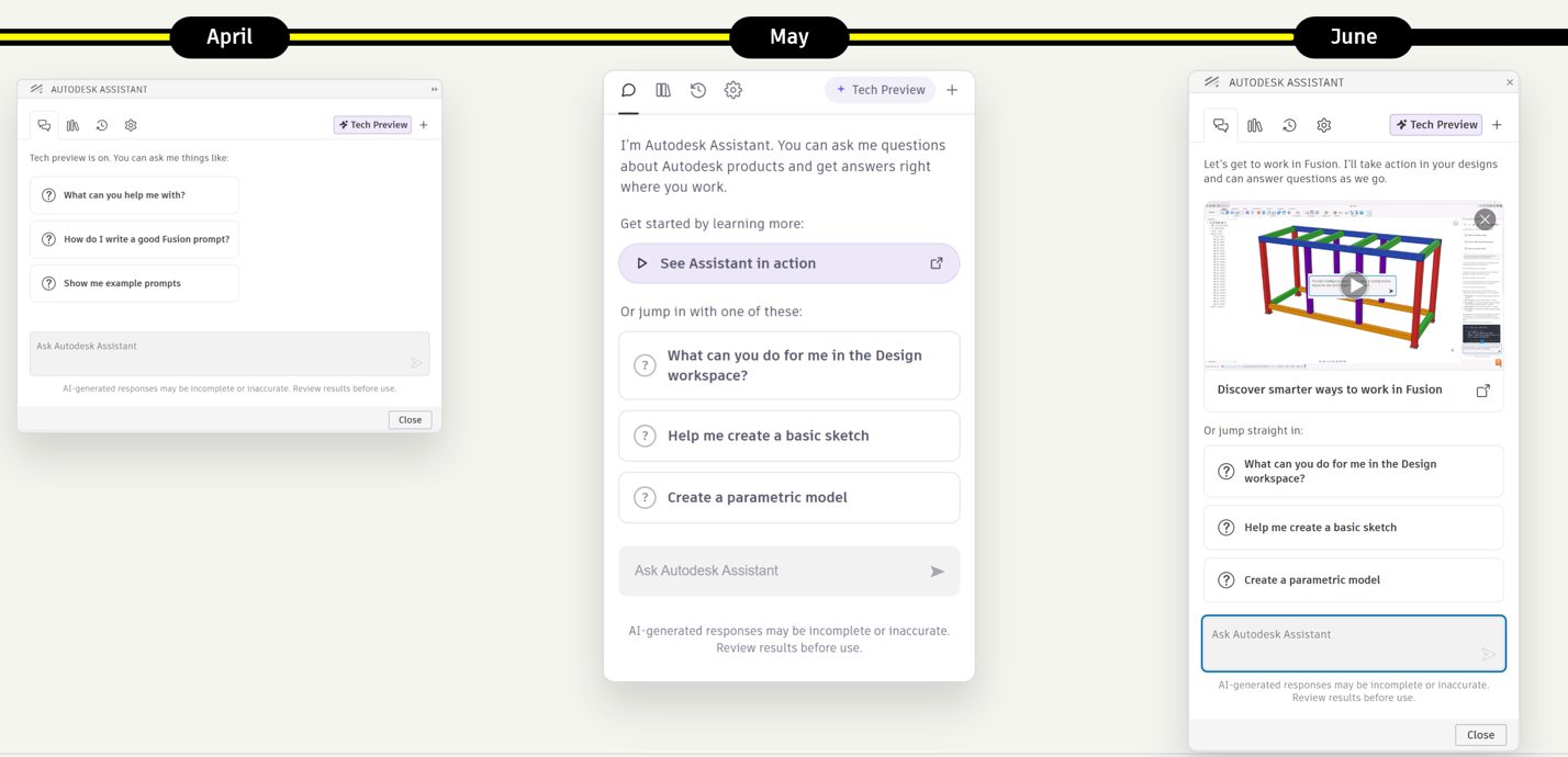
Right-Click Support for Autodesk Assistant
Autodesk Assistant now supports common right-click actions, including Cut, Copy, Paste, and Select All, within both the Assistant text input field and the canvas. This brings more familiar editing behavior to Assistant workflows and makes it easier to work with prompts and responses.
Workspace-specific workflow videos and file upload support have also been added to Autodesk Assistant, helping you discover recommended workflows and provide additional context when interacting with the Assistant.
Enhanced Sketch Visibility for Clearer, Brighter Sketching
Sketch visuals have been updated to improve clarity, contrast, and consistency across Fusion’s legacy visual environments, including Photo Booth, River Rubicon, and Dark Sky.
Updated sketch curve and profile colors make sketch geometry easier to distinguish, helping improve readability and visibility during everyday sketching workflows while maintaining existing sketch behavior and functionality.
Data Management
Autodesk Fusion is the connected platform for teams, unifying people, data, and processes so you can move faster, reduce errors, and innovate with confidence – and this update continues to bring more.
Learn more about Collaborative Editing (CE) enhancements here.
A refreshed Home experience in Fusion
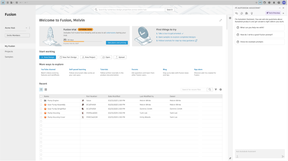
Fusion’s Home experience has been updated with a refreshed My Fusion page designed to make it faster and easier to start and continue work, access recent files, and discover helpful resources from one place.
Bringing recent work and actions together
One of the biggest changes in this release is that the previous Recent page is now integrated directly into My Fusion, creating a more streamlined starting point for everyday work. The updated layout also makes it easier to jump straight into work with quick-access actions for creating designs, including your default design type.
An experience that adapts to you
The experience also adapts based on the type of Fusion access you have and where you are in your Fusion journey. For example, users starting a Fusion trial see onboarding guidance through a curated list of first things to try, while more established users see a streamlined experience focused on quick access to recent work and common actions. The overall layout is also more responsive across viewport sizes, with added flexibility to adjust project space and work alongside Autodesk Assistant.
Looking ahead
This release is an important step toward a more adaptive and connected Fusion experience — one that helps users discover value faster, continue workflows more seamlessly, and navigate Fusion with greater clarity and confidence.
To learn more about the updated My Fusion experience, see this support article.
Keeping design context intact as work evolves
Share Links for Specific Points in Time
You can now create share links that capture a design at a specific point in time, instead of always showing the latest state. When viewing a historical point in a design using the panel in Fusion desktop or Fusion web, you can generate a share link that permanently opens that exact moment in the design history. Anyone who opens the link, including through embedded views, will see the design as it existed when the link was created. Standard share links created without selecting a point in time continue to work as before and will always display the latest state of the design.
Hub merge
Fusion now supports Hub Merge, making it easier to consolidate multiple Fusion hubs into a single destination hub for improved collaboration and data management. Hub Merge migrates projects, folders, members, designs, and drawings from a source hub into a destination hub, leaving nothing behind. This will help organizations reduce hub sprawl and centralize their data.
One of the most compelling benefits of Fusion Hub Merge is that it provides a self service way to consolidate multiple hubs into a single environment. While competing solutions often require costly consulting engagements, custom migration projects, or manual data consolidation efforts, Fusion Hub Merge enables administrators to unify projects, data, folders, and members directly within Fusion, reducing complexity, cost, and disruption for users.
Key things to know:
- Both hubs must be Collaborative Editing hubs.
- You must be a Hub Administrator in both hubs.
- The merge process is irreversible.
- Manufacturing tool and fastener libraries should be exported before starting the merge.
- All source hubs will no longer be available after the merge is complete.
Before merging, review the Hub Merge Best Practices Guide to ensure a smooth migration experience.
Moving to Collaborative Editing? Here’s what to expect
Collaborative Editing rollout
We are rolling out Collaborative Editing progressively across Fusion hubs. Before your hub transitions, admins will receive an email and all users will see an in-product notification with the rollout date. Once the update is complete, everyone will need to restart Fusion to access the new experience.
What you get with Collaborative Editing
- Editable Bill of Materials and Properties. Edit properties directly in the BOM or Properties panel. Changes are saved to the cloud, visible to teammates in real time, and tracked in design history.
- Shared part numbers. Manage multiple model variations under one shared part number to keep your BOM and property data aligned across the team.
- Versioning and history. Granular design history now tracks property and BOM changes alongside your save history.
- And more. Collaborative Editing also unlocks extended property search in Home Tab, Autodesk Assistant Tech Preview, and Custom Properties.
Want to learn more about Collaborative Editing? Check out:
- The new Fusion Collaborative Data experience
- Save Freely, Version Intentionally in Fusion
- Get answers to the questions your team will ask
Design
Find Similar Components (Design Extension)
Find Similar Components helps teams discover and reuse existing designs by searching across a Fusion hub for components with similar or identical geometry.
The command can be used on either assemblies or individual parts and returns results ranked by geometric similarity. Filters allow you to narrow results by project and control whether internal components are included in the search.
By helping teams identify existing alternatives before creating new parts, Find Similar Components can reduce duplicate content, improve data consistency, and simplify design library management.
Learn more about Find Similar Components.
Create Configurations On-Demand
Fusion now helps you create the product variations you need, when you need them, without prebuilding every possible combination.
In this first release, you can mark Theme Table columns as custom aspects with Customise, or revert them with Uncustomise. A new Test Row lets you try combinations before adding them as configurations.
When you insert, switch, or derive configurations, you can now create configurations on demand directly from the Select Configuration dialogue. Fusion reuses matching configurations when they’re available and creates new ones only when needed, nesting them under the appropriate parent rows.
Configuration Rules are enforced throughout the workflow, helping teams create valid, manufacturable variations with more control and less manual setup.
This first release supports Theme Table columns, with support for additional top table column types planned for future releases.
Learn more about Custom Configurations.
Improved PMI Import from STEP
Fusion now displays additional Product Manufacturing Information (PMI) when importing STEP files. This includes graphical PMI such as 3D annotations and Geometric Dimensions and Tolerances (GD&T) that were previously not displayed in some imported files.
This improvement helps ensure imported manufacturing information is represented more accurately, making it easier to review and work with supplier and customer data without missing important annotations.
Fastener Library Updates
The Fasteners Library has been expanded with new standard parts, including additional bolts, nuts, and inserts.
New inserts category includes molded-in, press-in, and ultrasonic thermal inserts, helping support a wider range of fastening methods commonly used in plastic part design. Additional industry-standard fastener families have also been added to the library, providing more out-of-the-box content and reducing the need for custom modeling.
Learn more about Fastener Library.
Threads Library
The new Threads Library allows teams to create, manage, and share custom thread definitions through a centralized hub-based library using the new Manage Threads command. Thread definitions automatically synchronize across devices, helping teams standardize custom thread specifications and reduce the need to recreate or manually distribute thread libraries. Custom threads can be used directly within existing workflows such as Hole and Thread.
Learn more about Threads Library.
Manage Lost Projections Now Supports Isoparametric Curves
Manage Lost Projections now supports isoparametric curves in Sketch. When an isoparametric curve loses its surface reference, you can quickly relink it to a new surface using the same familiar recovery workflow already available for projected geometry. Full API support is also included for automation and custom workflow development.
Learn more about projections in sketch and isoperimetric curves.
Construction Geometry
Perpendicular Planes on Curved Faces
The Plane Perpendicular to Face command now supports curved geometry, including cylindrical, conical, and toroidal faces. The plane orientation is calculated from the surface normal at the selected location, making it easier to create construction geometry directly from curved surfaces.
A new Reference Object input provides additional control over plane placement. When working with curved faces, point references such as vertices, sketch points, and work points can be used. For planar faces, planar faces and work planes can also be used as references. Sketches and sketch profiles are now accepted as inputs, and new Extend by Distance and Extend to Object options provide greater control over plane sizing.
Axis Perpendicular at Point has also been expanded to accept origin and construction planes as input references.
To use the command, open Construction Geometry > Plane Perpendicular to Face, select a planar or curved face, optionally choose a Reference Object to control placement, and use the extent options to define the size of the plane.
Learn more about construction geometry.
Plane Offsets During Creation
Most Construction Plane commands now include an Offset input directly in the command dialog, making it easier to position planes without creating additional reference geometry.
The offset value is entered during plane creation and remains editable through Edit Feature, helping maintain parametric flexibility as designs evolve. This also creates a more consistent experience across Construction Plane workflows, as the same offset behavior and dialog layout are now available in most supported commands.
Offset support is available across Construction Plane commands except Midplane, Plane Perpendicular to Face, and Plane Along Path.
Learn more about construction geometry.
Resize Construction Planes and Axes
New Resize controls are available across Construction Plane and Construction Axis commands, with two options: Default (fit to selection) and Extended (fit to view). The selected size is stored with the feature and can be updated later using Edit Feature, allowing construction geometry to adapt as designs evolve.
Previously, the visual size of a construction plane or axis was determined automatically when it was created, and changing it required recreating the feature. This update provides direct control over the display size and makes it easier to work with construction geometry in both small and large designs.
Public API support has also been added, allowing resize options to be used in automated workflows and custom add-ins.
To use the new functionality, open any Construction Plane or Construction Axis command and select either Default or Extended from the new Resize options in the command dialog.
Learn more about construction geometry.
More Predictable Selection in Construction Geometry
Selection behavior has been refined across Construction Geometry commands to make common workflows more efficient and consistent.
In commands where replacing a selection is a natural part of the workflow, you can now simply select a new entity to replace the current selection. This reduces unnecessary clicks and interruptions when refining inputs during command creation.
Commands that rely on sequential selection, such as Mid Plane, Plane Through Two Edges, Plane Through Three Points, and Plane Along Path, continue to use clear-and-reselect behavior to preserve predictable workflows and selection order.
These updates make Construction Geometry commands feel more consistent while maintaining the deliberate selection behavior required by multi-step workflows. In supported commands such as Offset Plane, Axis Through Two Planes, and Point at Vertex, selecting a new entity automatically replaces the existing selection. For multi-step commands, continue to clear an input before selecting a replacement.
Learn more about construction geometry.
Assembly Constraint Offset Limits in the Browser
A new inline edit button has been added to offset limit entries in the Browser. Clicking the button opens a focused dialog for editing minimum and maximum limit values, eliminating the need to open the full constraint editing dialog and making it faster to review and update offset limits directly from the Browser.
Learn more about assembly constraint offsets.
Mirroring of Construction Geometry
Following the addition of construction geometry patterning, Fusion now supports mirroring work planes, work axes, and work points.
This makes it easier to create and maintain symmetrical construction geometry while preserving parametric relationships. Mirroring is available in both parametric and Direct Modeling workflows, with API support included for automation and custom workflow development.
Learn more about the mirror and construction geometry.
Volumetric Lattice
New Honeycomb cell structure type in Volumetric Lattice Command
Honeycomb is a new cell type in the Volumetric Lattice command, enabling lightweight hexagonal lattice structures for efficient, manufacturable designs.
Learn more about volumetric lattice.
Beam improvements in Volumetric Lattice Command
Uniform Thickness is a new option available when non-uniformly scaling beams or 2.5D cells. It preserves the original beam diameter during scaling, preventing beam cross-sections from deforming into oval shapes. The feature also allows users to see the beams and wall thicknesses in millimeters, making thickness control much easier than before.
Learn more about volumetric lattice.
Drawings
Dimension Association for Center Marks
As part of making the drawing dimensioning system more stable, accurate, and reliably associated, we have improved dimension associativity behavior for center marks in Drawings. Previously, dimensions associated with center marks could become disassociated when center mark visibility was toggled on or off from the View Edit dialog. With this enhancement, associated dimensions are now automatically re-associated, improving annotation stability and reducing manual rework.
Tidy Up Improvement
Enhanced Tidy Up behavior for PCD and angular dimensions in Drawings. These dimensions can now be displayed at different positions, providing better spacing, improved clarity, and a cleaner dimension presentation.
Improved Drawing View Stability for Assembly Updates
Previously, when a new component was added to a sub-assembly using Edit In Place from the parent assembly, existing drawing views could incorrectly update to include the newly added component. Drawing views now maintain the correct component references and exclude unrelated components added later.
Centerline visibility after applying Break View
Improved break view update behavior for drawing views containing centerlines. Previously, modifying the break view gap could cause centerlines to revert to their original full length. With this enhancement, centerlines now maintain the expected shortened representation after break view updates.
Flip Arrow Positions
Improved dimension editing behavior to preserve flipped arrow positions while editing dimension text. Previously, flipped arrows could revert to their original positions after users added or updated additional text in the dimension. With this enhancement, arrow positions are now maintained correctly throughout the editing workflow.
Electronics
Altium Project Import
You can now translate Altium Designer projects directly into Fusion Electronics, making it easier to migrate existing designs and continue development in Fusion. The translator imports key project data, including schematics, PCB layout, components, nets, footprints, layers, and design structure, helping preserve design intent while reducing manual recreation work. This streamlines onboarding for teams moving from Altium to Fusion and enables a faster, more reliable transition of existing electronics projects into the Fusion workflow.
Unified Restrict Layers for Copper Restrictions
We’ve simplified copper restriction management by replacing separate Restrict Top, Restrict Bottom, and Restrict Vias layers with a single generic Restrict Layer. Restrict polygons now use a new Restrict Layers property to define which routable copper layers they affect, with support for one or multiple target layers, automatic color matching, white pattern fill for multi-layer restrictions, and visibility tied to hidden routable layers. Additionally, a new Restrict Area command lets you draw restrict polygons directly, choose affected layers, and create cutouts when enclosed within matching restrict shapes.
BSDL Component Generator
We are pleased to introduce the Component Generator in the Electronics Library. This release enables the automatic generation of QFP, SOIC, QFN, and BGA package components by parsing data directly from a provided BSDL (Boundary Scan Description Language) file.
This capability significantly reduces the time and effort required to create large, high-pin-count components, allowing them to be generated in seconds.
Key Capabilities
- One-Click Component Generation: Automatically generate complete components, including the appropriate symbol and footprint, from a BSDL file.
- Flexible Customization Options: Easily configure component type, pin-to-pad mapping, pin directions, and other settings through an intuitive command dialog.
- Editable Package Parameters: Modify default package dimensions and parameters as needed to meet specific design requirements.
- Real-Time Validation and Feedback: Receive immediate in-command feedback and validation when entered values or customizations are invalid or inconsistent.
- Quick Reset Functionality: Restore all settings to their original state at any time using the built-in Reset option.
- Integrated BSDL Reference View: Access the parsed BSDL content directly within the command for convenient review and verification.
With the Component Generator, creating complex electronic components is faster, more accurate, and more efficient than ever before, providing greater control and flexibility while significantly streamlining content creation workflows.
Flexible schematic sheet naming
Electronics sheet names can now use mixed case and spaces, aligning them with broader Fusion naming conventions. This makes schematic organization clearer and more readable—for example, names like “Power Supply” or “Main Controller” are now supported instead of being forced into uppercase, no-space formats. Existing sheet names remain supported, while new names can better reflect user intent and project structure.
Layerstack view support for multiple PCB assemblies
The Layerstack view now supports assemblies with multiple PCBs and automatically updates. This improves visibility for electronics assemblies that include more than one PCB.
Expanded Command Execution Support for Selections
More commands can now be started directly from your current selection. Now when a group is selected, you can now execute Arrange, Pattern, Change Attribute Set, Fanout Devices, Pin Breakout Devices, and Replace Components from the right-click context menu. This expands the range of commands available for multi-object selections, providing more direct access to common editing workflows.
Sustainability
New Insights
Sustainability Insights provides carbon emissions information to help users make more informed design and manufacturing decisions. The information can support sustainability reporting and compliance workflows, including carbon computation frameworks and Digital Product Passport documentation. Sustainability information is available from Utilities in the Design workspace, under Inspect, and through Autodesk Assistant.
Simulation
Enhanced Meshing for Extruded Solids (Simulation Extension)
The structural meshing algorithm has been improved for solids of extrusion. Fusion now automatically creates more uniform meshes on this geometry type, improving robustness, mesh quality, and workflow speed in structural simulation. No workflow change is required.
Injection Molding result accuracy improvements (Simulation Extension)
The injection molding solver has been updated to better handle some uncommon molding conditions. Because of these improvements, you may notice different warpage results in certain simulations compared to previous versions. The goal is to provide more reliable predictions while keeping existing workflows unchanged. Available with the Simulation Extension.
Manufacturing
3+2 Clearing Toolpath Strategy (Manufacture Extension)
A new 3+2 Clearing toolpath strategy is now available. This strategy removes stock from multiple fixed 3+2 orientations within a single toolpath, helping reach overhanging regions and areas that may otherwise be inaccessible due to tool holder constraints.
Machining directions can be defined manually, generated automatically, or created using a combination of both methods, giving you flexibility in how the toolpath is generated. You can also choose between different clearing styles, including Pocket, Adaptive, and Parallel.
The strategy supports the use of a virtual fixture to limit the toolpath where required, with user-defined height and lateral extents. In addition to 3+2 machining workflows, the strategy can also be used in 3-axis mode.
Blend entry and exit passes
Blend now supports additional passes before the start drive curve and after the end drive curve when Stepover Calculation is set to From tip of tool. These added passes extend the machined area beyond the defined drive curves, improving finishing flexibility and giving users better control over how the tool approaches and leaves the part.
Ramp: Machine Shallow Areas
Ramp now supports machining shallow areas in a way similar to 3D Contour. You can enable Machine Shallow Areas on the Passes tab, and Fusion adds extra stepdowns to limit stepover in shallow regions. This improves toolpath coverage without requiring you to switch strategies.
Rotate Individually in Move
The Move command now includes a Rotate Individually checkbox. When enabled, selected components rotate about their respective local axes instead of rotating through shared behavior. This reduces repetitive repositioning work when arranging parts for manufacturing setups and fixture preparation.
Learn how to move or rotate a component in a build volume.
Additive Manufacturing
Arrange Sub Nest
Arrange Sub Nest lets you group selected parts into compact reusable sub nests. Selected components are automatically arranged into a specified or auto calculated volume, creating a smaller grouped arrangement that can be reused later with Arrange as part of a larger layout. This supports grouped handling of small or delicate parts and works with the 3D Printing Essentials app to create sinter boxes.
Note: a manufacturing model is required to use the Arrange Sub-Nest feature.
Learn more about Arrange Sub Nest.
Slice Analysis for Layer Area Variation
Slice Analysis visualizes the laser scanned cross sectional area for each printed layer. This helps users identify large layer to layer area variation that can indicate thermal instability concerns, including risk of warping, residual stress, and distortion. Slice Analysis is available for MPBF, MJF, and SLS additive technologies.
Learn more about Slice Analysis statistics.
Gyroid infill density fix
Gyroid infill now scales more consistently as density values are increased in Print Settings. This resolves an FFF issue where Gyroid infill density did not increase above 41%.
Improved additive simulation legend visibility
Additive simulation legends are now easier to read in dark Fusion themes. A theme aware background box has been added behind the additive toolpath simulation legend, improving contrast in environments such as River Rubicon and Dark Sky.
MPBF process simulation now native on Apple Silicon (Manufacture Extension)
Additive MPBF Process Simulation now runs natively on Apple Silicon Macs without depending on Rosetta. This keeps existing simulation workflows available for Mac based teams with no expected disruption. In the API, this capability is referred to as Additive FEA. This is a Manufacturing Extension capability.
General Improvements
Legacy Toolpath Calculation Format Option
Fusion is transitioning the data format used between the client and the toolpath calculation component. An optional setting allows you to revert to the legacy communication format for calculation when troubleshooting missing or incorrect calculation input data. The toolpath calculation log indicates whether the new format was used. This should be used only as a troubleshooting fallback, not as a general workflow change.
In Process Stock undo and redo preserves prior results
Undo and redo are now supported for In Process Stock calculations in Manufacture. Fusion preserves existing IPS results where possible instead of invalidating the full result, and only operations affected by the reverted change need to be recalculated. No workflow change is required.
API
TypeScript Support (Beta)
Fusion API now supports TypeScript alongside Python and C++. This gives developers a modern scripting and add-in workflow with strong typing, local development, and the same full debugging experience available in existing Fusion API workflows. TypeScript support also improves Automation API development by allowing teams to build and debug locally before submitting jobs. Scripts and add-ins run in a sandboxed environment with configurable read and write permissions.
Expanded Construction Geometry API Support
New API support includes resizing construction planes, reference-object workflows for Plane at Angle, and expanded Plane Along Path functionality with additional extent and placement controls. These updates enable more advanced automation, scripting, and add-in development scenarios.
Drawing API Enhancements
Added API support for custom sheet sizes and support for creating drawings from templates through the Drawing API workflow.
Mesh Compare
A new meshBody.meshCompare API method enables add-ins to compare one mesh body against another and return deviation data. This supports validation and comparison workflows where teams need to quickly detect, visualize, and communicate differences between mesh geometry. Deviation results can be visualized through color mapping.
Enhanced the API Support for Sketch Auto Constrain
We’ve enhanced the Sketch AutoConstrain API preview to give you greater choice and flexibility.
There are now three result type options to choose from.
- Option 1: default option provides the most thorough constraints and dimensions (slowest).
- Option 2 returns high-quality, fast results (quickest).
- Option 3: Choose the tolerance-based option to allow small geometry adjustments that help create a fully constrained sketch.
This functionality is provided as a preview of intended future API capabilities. You are encouraged to use it and report any problems or suggestions using the Fusion API and Scripts forum.
Release Notes
To see more fixes, minor enhancements, and keep up with the latest check out our Release Notes for more information on changes to Fusion and Fusion web client.
Insider Program
Do you want to engage more with the Autodesk community? Check out the Fusion Insider program to use exclusive previews, and test out the latest build before it’s released to the public.
As a member, you’ll gain inside knowledge of updates and a first look at new features. You’ll also be able to join exclusive events and try pre-release functionality. Plus, you can give feedback directly to the product teams.