 Jim Byrne
Learn how geometric dimensioning and tolerancing (GD&T) works, where traditional 2D documentation can create challenges, and how Autodesk Inventor’s model-based definition (MBD) tools help connect design intent, manufacturing, and inspection through annotated 3D models.
Enhance Your Engineering Workflows
Precise, powerful, and ready for innovation with Autodesk Inventor.
What is GD&T and why does it matter?
For more than a century, manufacturers have relied on engineering drawings to communicate design intent from engineering to manufacturing. Geometric dimensioning and tolerancing (GD&T) was developed to make that communication more accurate by providing a standardized symbolic language for defining how a part should be manufactured, assembled, and inspected.
GD&T helps engineers describe not only the size of a feature but also its allowable variation in form, orientation, location, and profile. By using a common language defined by standards such as ASME Y14.5 and ISO 1101, designers, machinists, suppliers, and inspectors can work from a shared understanding of functional requirements.
While geometric dimensioning and tolerancing improves engineering communication, applying it solely through 2D drawings can create challenges. Annotations, datums, and manufacturing notes are often distributed across multiple drawing views, requiring downstream teams to interpret how those requirements relate to the physical 3D part.
Model-based definition (MBD) addresses this challenge by associating GD&T and other product manufacturing information (PMI) directly with the 3D model. Autodesk Inventor includes MBD capabilities that allow manufacturers to create annotated 3D models while continuing to support drawing-based workflows where they remain necessary.
This guide explains how GD&T works, why datums and tolerance schemes matter, how MBD supports manufacturing workflows, and how Autodesk Inventor helps teams manage product definition throughout the design and manufacturing process.
What is GD&T?
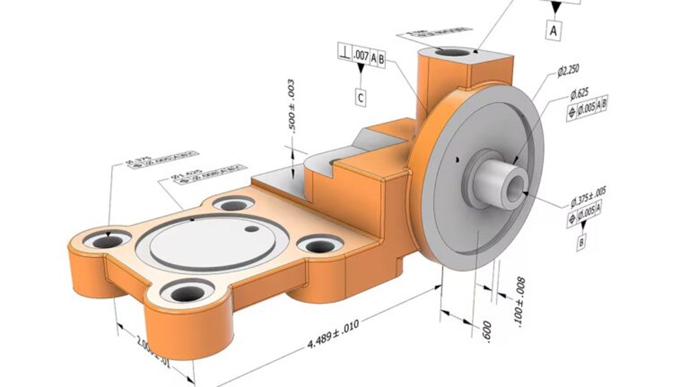
Geometric dimensioning and tolerancing (GD&T) is an engineering language used to specify the allowable variation of manufactured features. It is governed by internationally recognized standards, including ASME Y14.5 and ISO 1101.
Instead of relying exclusively on plus-or-minus dimensions, GD&T uses symbols, feature control frames, and datums to communicate functional requirements more clearly. These controls help define how features relate to one another and how a part should perform when assembled.
GD&T is especially valuable in products where fit, alignment, movement, or interchangeability are important.
GD&T vs. traditional coordinate dimensioning
Traditional coordinate dimensioning often locates features using nominal dimensions and allowable variation in X and Y directions.
Geometric dimensioning and tolerancing takes a different approach by defining tolerance zones that align more closely with how a feature functions. For example, a position tolerance on a hole can define a cylindrical tolerance zone around its intended location rather than separate coordinate limits.
Because these tolerance zones are tied to functional requirements, engineers can often communicate design intent more effectively while providing manufacturers greater clarity regarding acceptable variation.
GD&T also explicitly references datums, reducing ambiguity about how parts should be measured and inspected.
The 5 categories of GD&T controls
GD&T symbols generally fall into five categories:
Form
Controls the shape of an individual feature without reference to other features. Common controls include:
- Straightness
- Flatness
- Circularity
- Cylindricity
Orientation
Controls the angular relationship of a feature relative to a datum. Common controls include:
- Parallelism
- Perpendicularity
- Angularity
Location
Controls the position of features relative to datums. Common controls include:
- Position
- Symmetry
Runout
Controls variation as a part rotates about a datum axis. Common controls include:
- Circular Runout
- Total Runout
Profile
Controls the allowable variation of complex shapes and surfaces. Common controls include:
- Profile of a Line
- Profile of a Surface
Among these controls, position tolerances are widely used to define the location of holes, slots, and mating features in manufactured assemblies.
What are datums?
A datum is a theoretically exact reference point, axis, or plane used to establish a measurement framework.
Datums create a consistent coordinate system for manufacturing and inspection. They define how parts should be oriented during measurement and help ensure everyone evaluates the part using the same reference structure.
In a typical datum reference frame, primary, secondary, and tertiary datums work together to fully establish a part’s orientation.
When datum structures are clearly defined, manufacturing and inspection teams can more consistently evaluate whether a part meets design requirements.
What is a feature control frame?
A feature control frame is the symbolic annotation used to communicate GD&T requirements.
Feature control frames typically include:
- A geometric characteristic symbol
- A tolerance value
- Optional material condition modifiers
- Datum references
Understanding how to read feature control frames is fundamental to interpreting geometric dimensioning and tolerancing correctly.
Challenges of applying GD&T on 2D drawings
GD&T communicates three-dimensional requirements, yet those requirements are often presented on two-dimensional drawings.
As products become more complex, engineers and manufacturers may need to reference multiple drawing views to fully understand how tolerances, features, and datums interact. Curved surfaces, intricate geometries, and multi-part assemblies can make interpretation more difficult.
Additionally, drawings and models must often be maintained together. When designs change, documentation must be updated and reviewed to ensure consistency across deliverables.
These challenges do not make drawings obsolete, but they have contributed to broader adoption of model-based definition workflows in many manufacturing organizations.
How GD&T helps manage tolerance stack-up
Tolerance stack-up occurs when variation from multiple components accumulates across an assembly.
Even when every individual part meets specification, combined variation may affect assembly fit, alignment, clearance, or performance.
GD&T helps address stack-up by:
- Establishing consistent datum structures across mating components
- Defining feature relationships more clearly
- Supporting the use of material condition modifiers where appropriate
For organizations performing tolerance analysis, tools such as the Autodesk Inventor Tolerance Analysis environment allow engineers to evaluate how dimensional variation may affect assemblies before manufacturing begins.
This analysis can help teams identify critical dimensions, assess design robustness, and make more informed tolerance decisions.
How GD&T supports quality and inspection
GD&T provides a structured framework for inspection by defining how features should be evaluated relative to datums and allowable variation.
Inspection teams can use GD&T annotations to develop repeatable measurement procedures and coordinate measuring machine (CMM) inspection strategies.
When product manufacturing information is embedded within a model-based definition workflow, downstream inspection software may be able to leverage that information directly, depending on the tools and processes being used.
This can help improve consistency between design intent and inspection execution.
How model-based definition connects GD&T to the 3D model
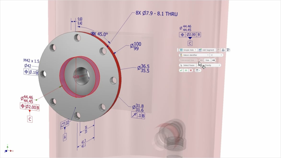
Model-based definition (MBD) embeds product manufacturing information directly within the 3D model.
PMI can include:
- GD&T annotations
- Datums
- Surface finish requirements
- Material specifications
- Manufacturing notes
Instead of locating information across multiple drawing views, engineers can associate annotations directly with the geometry they describe.
This creates a more connected representation of product intent and can help improve communication among design, manufacturing, suppliers, and quality teams.
How Autodesk Inventor supports GD&T and MBD
Autodesk Inventor includes tools that support model-based definition workflows and standards-based geometric dimensioning and tolerancing practices.
With Inventor, teams can:
- Apply GD&T annotations to 3D model geometry
- Create datum reference features
- Manage product manufacturing information within the model
- Produce associated drawing documentation when required
- Export models for downstream manufacturing and inspection workflows
Inventor supports commonly used standards, including ASME Y14.5 and ISO 1101, enabling organizations to create product definitions aligned with industry practices.
For organizations sharing manufacturing information externally, Inventor also supports formats such as 3D PDF and STEP AP242, helping facilitate communication across engineering ecosystems.
What to look for in GD&T software
When evaluating GD&T software, manufacturers often look for:
- Native 3D annotation: The ability to attach GD&T directly to model geometry.
- Standards support: Compliance with recognized standards such as ASME Y14.5 and ISO 1101.
- MBD capabilities: Support for product manufacturing information within a model-centric workflow.
- Tolerance analysis: Tools that help evaluate dimensional variation across assemblies.
- Interoperability: Support for industry-standard file formats used by suppliers, manufacturing teams, and inspection systems.
Autodesk Inventor provides these capabilities within an integrated product development environment.
Connecting design intent across the product lifecycle
Manufacturing organizations increasingly rely on digital workflows that connect design, manufacturing, quality, and supply chain activities.
As these processes become more data-driven, model-based product definitions can help improve consistency and make information more accessible throughout the product lifecycle.
GD&T remains the foundation for communicating engineering requirements. MBD extends that foundation by associating those requirements directly with the 3D model.
With Autodesk Inventor, organizations can adopt model-based practices while continuing to support established documentation workflows, helping teams improve communication without requiring an immediate transition away from drawings.
Frequently asked questions
GD&T is a standardized engineering language used to define allowable geometric variation in manufactured parts. It helps communicate functional requirements more clearly than dimensional tolerancing alone and is governed by standards including ASME Y14.5 and ISO 1101.
Some of the most commonly used GD&T controls include Position, Flatness, Perpendicularity, Parallelism, Circularity, Runout, and Profile. Position tolerances are particularly common for holes, slots, and mating features.
A datum is a theoretically exact reference point, axis, or plane used to establish a measurement framework. Datums help designers, manufacturers, and inspectors evaluate parts using the same coordinate system.
Yes. GD&T has traditionally been applied on engineering drawings and remains widely used in drawing-based workflows. MBD extends GD&T by associating those annotations directly with 3D model geometry.
Inventor provides tools for creating GD&T annotations, defining datums, managing PMI, supporting model-based definition workflows, and exchanging manufacturing information through industry-standard formats such as STEP AP242 and 3D PDF.
Design engineers, manufacturing engineers, quality teams, suppliers, and inspection specialists can all benefit from clearer communication of product requirements and more connected product-definition workflows.
No. GD&T can benefit organizations of all sizes by improving communication of engineering requirements, reducing ambiguity, and supporting more consistent manufacturing and inspection practices. Small manufacturers often use the same GD&T standards as larger enterprises to ensure product quality and interchangeability.