Discover the September 2025 update, featuring dark mode, powerful new parametric text tools, GPU-based stock simulation, and more.
v.2604.1.48 – October 8, 2025
Data Management
- Resolved an issue where the version icon was displayed instead of the revision icon when a design had been revised.
Design
- Improved stability when using Insert Fasteners.
- Previously, no gap was added between the dimension text and the Feature Control Frame, which caused overlapping with the dimension text (especially in ISO where the dimension line is placed below the text). Now the gap is handled correctly and GD&T symbols are displayed as expected.
- Resolved an issue in configurable assemblies where directly updating a configured component with multiple instances in the assembly would result in an extra reference in the assembly.
Electronics
- Resolved an issue that prevented saving new libraries and caused placement inaccuracies when copying footprints from a legacy library to a new one with extended layers support. New libraries can now be saved correctly, and all signal objects are placed on the appropriate layers.
- Resolved an issue where you could no longer change the destination layer when importing DXF/DWG files into a board design.
Manufacturing
- Resolved an issue where Fusion could crash if document changes were made while rest surfaces were generating in the background.
- Resolved an issue where toolpaths using mesh geometry would fail to generate in some circumstances.
v.2604.1.25 – September 22, 2025
Onboarding (New Users)
- The intent screen now includes questions about your industry, team size, navigation, and setup preferences to tailor the product experience.
- The trial sign-up process has been streamlined to provide faster access to Fusion.
- The Quick Setup dialog has been retired across many workspaces but will continue to serve video learning content in the Simulation and Generative Design workspaces.
Design
- Resolved an issue where disabling the ‘Spacebar Repeats Last Command’ preference did not maintain the spacebar assignment for the previously selected assignment. Instead, users would encounter a notification indicating that the shortcut was unassigned, even though the preference was correctly set.
- Fixed an issue where configuration data could become corrupt and cause missing data in tables. This fix repairs the corrupted data and notifies you upon opening the Configured Design. Missing values are restored, and you will see restored rows marked with ‘(restored)’ for your review.
- Fixed an issue where closing a document could trigger an incorrect recover configuration dialog.
- Resolved an issue where the configuration table became unresponsive.
- Resolved an issue causing bad thumbnail creation for certain designs.
- Fixed an issue where saving constraints in joint systems occasionally failed, even though previews looked correct. The system now ensures constraints are applied in the right order, improving reliability and consistency between preview and commit.
- Restored visibility of the “Select Referencing Joints” option.
- Enabled opening of previously inaccessible configuration files.
- Fixed an issue within Sheetmetal where the >SHEET placeholder did not correctly display the sheet’s name.
- Fixed an issue with right-mouse-clicking a Component Browser node on macOS where its context menu disappeared as soon as it opened.
- Improved stability during mouse drag operations.
- Improved stability on macOS.
Manufacturing
- Fixed an issue where an angle exceeded the machine’s axis limits in Turning toolpaths.
- Improved stability when creating or editing Turning Thread toolpaths.
- Enhanced tooltip behavior when hovering over toolpath status badges.
- Improved tool selection accuracy in the toolpath UI dropdown.
- Fixed an issue with certain turning trace toolpaths that were incorrectly giving an error
- Fixed 2D Chamfer Toolpath calculation error in duplicated manufacturing models.
Electronics
- Fixed a crash in Skia/Qt graphics caused by changes in the drawing layer sequencer.
v.2604.0.316 – September 8, 2025
Backwards Compatibility Notice: This version includes changes that are not backward compatible with previous versions. To ensure smooth data sharing and collaboration, please update to the latest build.
Table of Contents
- Highlights
- Usability
- Data Management
- Design
- Drawings
- Electronics
- Simulation
- Manufacturing
- API
- Insider Program
- Release Notes
Highlights
This September we have some fantastic improvements and features that we think you’re going to love. Whether you’re eagerly waiting for Dark Mode, looking to streamline your data management with new collaborative editing options, or ready to explore new design tools like Parametric Text and Rounded Thicken, there’s something here for everyone. Plus, we’ve added great enhancements in drawings, electronics, and manufacturing to help you work more efficiently and creatively. Let’s dive into some of the highlights from this release.
Usability
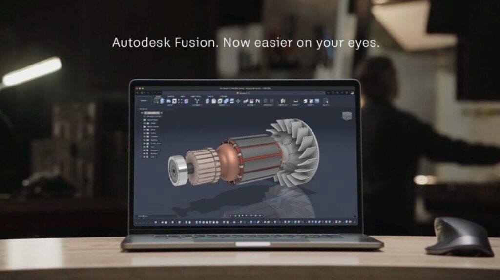
- Dark Mode Goes Live
- New UI Theme Matching
Data Management
- Numerous Hub Enhancements
- Properties Support in Drawings Title Blocks (Collaborative Editing)
- Configurable Change Management (Fusion Manage Extension)
Design
- New Parametric Text
- New Rounded Thicken
- New Fastener Micro Editor
- Enhanced Configurations
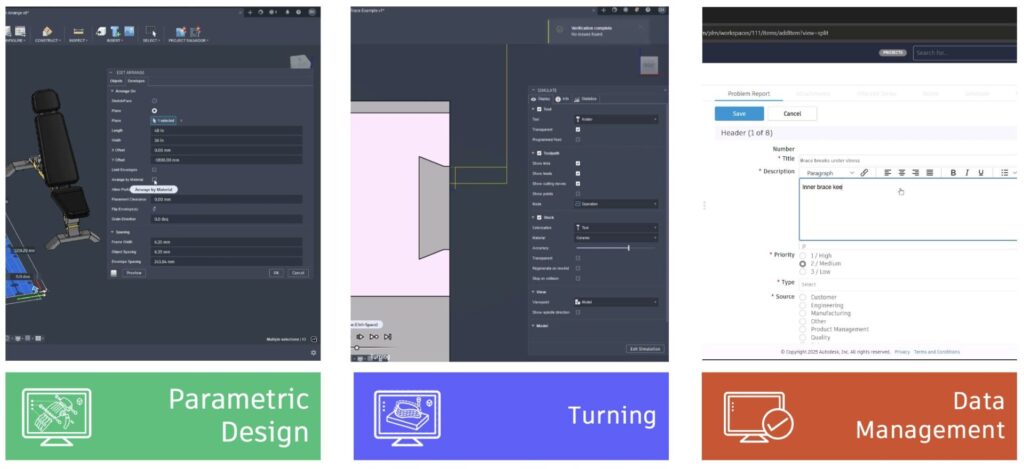
- Arrange by Material (Manufacture Extension)
Drawings
- Automated Center Mark Pattern
Electronics
- Enhanced Layer Support
- Fully Delete Component
- Show Measurement Details in 3D PCB
Manufacturing
- [Windows] GPU Based Stock Simulation
- New Threadmill Definitions
- New Turning Enhancements
- New Additive eBeam
Usability
UI Themes General Availability
Preferences > General > Theme > Dark Blue
The moment many of you have been waiting for is finally here! Dark mode, along with other UI themes, is now officially available for everyone. No need to enable the preview feature – it’s ready for you to enjoy a fresh, new look right away.
To switch to dark mode or other UI themes, simply go to the General section of your preferences. You’ll find a new Theme option there. Change from Fusion Classic to Dark Blue and click “OK” to experience Fusion in a whole new light.
A quick note: If you previously adjusted the Display Settings Environment to a custom canvas color, your settings will remain unchanged. If you’d like the canvas color to match your selected UI Theme, head over to the Navigation Bar > Display Settings > Environment and choose Theme (default).
UI Themes: new Match Device Theme option
Preferences > General > Theme > Match Device Theme.
As of this update a new option is now available as part of the UI Themes that allows Fusion to inherit the light/dark mode setting from your operating system. OS light mode corresponds to Fusion’s Light Gray theme, while OS dark mode corresponds to Fusion’s Dark Blue theme. If you are the type of person who configures your device theme to change with the time of day, this is the option for you!
Use Spacebar to activate Repeat Command

Spacebar to Repeat Last Command is here at last. By default, Fusion will now reserve Spacebar for this purpose. If you previously had a different command assigned to Spacebar and wish to reassign it, open Preferences > General > and uncheck Spacebar repeats last command near the bottom of the list to un-assign Repeat Last Command and free the Spacebar for reservation by another command.
Learn more about what Keyboard Shortcuts are available.
Increased Trackpad Zoom Speed for macOS
We increased the zoom sensitivity for trackpad input from 1.0 to 3.0. This should make zooming on the canvas with a Mac trackpad much faster.
Tip: Too fast? Not fast enough? You can experiment with the value that feels best to you by using the text command Options.SetTrackpadZoomSpeed N where N is a numerical decimal value. After changing this value, use options.save for it to persist across sessions.
Enhanced Graphics Handling
We’ve enhanced Fusion’s graphics handling to automatically prioritize your most powerful graphics card. If you have a computer with multiple graphics cards (like a laptop with both integrated and discrete graphics), Fusion will now by default select and use the discrete graphics card for optimal performance.
Performance
We’ve made some updates to our platform that will make your design work smoother and faster. Check out the latest improvements:
- Saving & Exporting F3D Single Designs:
- Save/Save As: Performance improved up to 45%
- Export: Up to 4x faster, with file sizes reduced by up to 35%
- Opening Designs after Save: Opening an F3D single design after saving up to 6% faster
- Opening Large Assembly Designs: Now up to 40% faster when opening typical large assemblies.
- Switching Designs: Switch between large files up to 50% faster
- Compute All: Calculation times reduced by up to 20%
- Rectangular Patterns with Components: Creation is now up to 10% faster
- Checking Properties: Properties dialog opens up to 5x faster
- Editing Extrude: Up to 12x faster for some files
- Editing Emboss: Up to 15x faster on certain designs
- Copying Sketch Objects: Copy large sketch elements up to 14x faster
Note: These improvements are observed using datasets provided by our customers, and the performance gains can vary depending on the specific dataset.
Data Management
Updated Desktop Connector for Fusion
We’re excited to announce enhancements to Desktop Connector for Fusion, launching in late September. Development projects often involve various files. Desktop connector gives you a virtual Fusion drive on your Windows desktop so you can easily store files in your Fusion project and access them from anywhere. Enhancements include reduced upload times, in-progress uploads immediately show in Windows Explorer, and a new upload with references workflow for SolidWorks and Inventor, making it easier than ever to manage your designs. Plus, you’ll find many usability enhancements that streamline your experience and boost productivity.
Hub Visibility
For those of you who are logged in with a private company email domain, you will soon have the ability to view all the hubs created within your company. Through the Fusion web client settings, you can access a read-only list of all hubs, making it easier to keep track of their digital landscape. Additionally, a self-serve downloadable list will allow you to export this information for consolidation purposes. Keep an eye out for this valuable update and take advantage of the improved visibility for more efficient workspace management.
Configurable Change Management (Fusion Manage Extension)
Fusion Manage Extension is getting a big power-up this September. As of this update Manage Extension customers can now configure their PLM processes with even greater precision and flexibility. To do this we are introducing new workspaces related to change management, quality management, supplier collaboration, and new product introduction. The Manage Extension will now support expanded change management processes, including problem reports, change reports, and change tasks, ensuring a comprehensive end-to-end management solution.
Additionally, the Change Order process has been upgraded to support more properties and offer more robust and comprehensive workflows. These updates provide you with powerful tools to tailor PLM processes to your specific needs, driving efficiency and productivity in your organization.
Collaborative Editing Enhancements
Learn about Collaborative Editing.
Save As Enhancements (CE)
We’re enhancing Fusion’s Shared Part Number (SPN) system to support better data duplication handling. This includes a new option for part number in Save As and Replace and Save Copy As dialogs, as well as better property handling for ‘Save As and Replace’ and ‘Save Copy As’ workflows.
Properties Support in Drawings Title Blocks (CE)
You can now place new concurrent Properties (attributes) in the Title Block of Drawings. We’ve updated the UI to include a drop-down menu for Type and attributes for different property groups. These new properties are available in both templates and drawings for ISO and ASME standards. Plus, the “Drawn By” and “Drawn Date” attributes in ISO drawings and templates have been renamed to “Created by” and “Created Date,” respectively. The “Project” attribute is now labeled as “Project Folder”.
Properties in View tab in Fusion Web Client (CE)
In the latest Fusion Web Client update, we’ve made it even easier to access the properties of root components. Now, you can effortlessly view these details under the View tab in the property panel. This enhancement ensures you have quick and straightforward access to vital information, helping you streamline your projects and workflows.
Configure Internal Component Properties (CE)
In July, we enabled the workflow that lets you configure properties for internal components in a Configured Design in Collaborative Editing hubs. In this release, we’re adding some fit and finish support for the following workflows in the Properties tab of the Configuration Table, to make this workflow easier for you to:
- Expand All
- Collapse All
- Sort Components (A-Z, Z-A, Design Order)
- Show/Hide individual property columns
Updated Version and Revision Iconography (CE)
The updated Version and Revision Iconography introduces fresh icons to clearly indicate different versions and revisions of documents, making it easier for you to identify and manage document changes at a glance. This simplification ensures that at the document level, you only need to recognize the existence of a version, with more detailed information available in the model browser.
Consistent iconography is maintained across different contexts, such as the data panel and model browser. The refresh process is more passive, and detailed version icons indicate whether it is the latest version, if there are new changes beyond the version, or if a new version hasn’t synchronized yet. Plus, tooltips offer additional information to keep you well-informed.
Looking ahead, don’t miss the chance to join us at Autodesk University, either in-person or online, to discover the exciting data projects we’re working on.
Design
New Parametric Text
You can now create and use Text Parameters in sketches, features, and configurations. To create a Parameter with a Text unit type, simply add text to a Sketch to automatically generate a new text model parameter. Alternatively, you can use the Modify > Parameters dialog to create a new user parameter with the Text unit type, then reference it in a sketch or add it to the Configuration Table.
Here’s how it works: wrap plain text in single quotes (‘), and to reference an existing text parameter, type the parameter name and select it to add it to the expression. To string together existing text parameters, add a (+) between each parameter.
Here are some examples of text parameter expressions:
- Example 1: ‘Example text’
- Example 2: ‘Example text’ + ExistingTextParameter1
- Example 3: ExistingTextParameter1 + ExistingTextParameter2
With these new capabilities, you can better organize and manage text within your designs, making it easier to customize and automate your design workflow.
Learn more about Text parameters.
New Rounded Thicken
We’re excited to introduce the Rounded Thicken option for the Design > Create > Thicken tool, offering you the flexibility to choose between sharp and rounded options. This works similarly to the rounded shell and rounded offset functionality, giving you more control over your designs.
Learn more about Thicken.
Enhanced Edit in Place
Unlock enhanced Edit in Place capabilities for a smoother workflow across Solid and Mesh modeling in the Design workspace.
In the SOLID workspace, you can now effortlessly edit your models with new right-click (RMB) options. Edit the initial position, create selection sets, control texture maps, export, save copies, and replace components—all with a simple right-click on the component. For root components, switch to Direct Modeling with ease. Assemble your designs faster with new options to link motions, enable and disable contact sets, and create new contact sets. Plus, you can now insert fasteners, decals, and meshes directly.
In the MESH workspace, new capabilities let you insert meshes and create mesh section sketches seamlessly. Prepare your models with enhanced repair options. Modify your meshes with new tools to reduce, scale, and convert them to fit your needs.
Learn more about Edit in Place
AutoConstrain Enhancements
AutoConstrain can now predict symmetric constraints in more instances. When symmetric geometry is present in a sketch, a symmetric constraint will be applied and shown as a possible result.
Learn more about AutoConstrain.
Flange and Lofted Flange Improvements
We’re thrilled to bring you some exciting updates to the Flange tool that are all about making your experience smoother and more intuitive.
- Easier Access to Lofted Flange: You can now find the Lofted Flange command right in the Create menu on the Sheet Metal tab. Plus, you can pin it to your Ribbon/Toolbar for quick access!
- Better Tooltips: We’ve spruced up the tooltips for both the Flange and Lofted Flange commands to give you clearer and more helpful guidance.
- Clearer Command Dialogs: You’ll notice specific command dialog titles for both Create and Edit workflows for the Flange and Lofted Flange. This should make things much easier to navigate.
- Unique Timeline Icon: The Lofted Flange now has its very own unique timeline icon, so you can spot it right away.
These improvements are all about creating more tailored pathways and providing precise help, so you can enjoy a more streamlined design journey.
Enhanced Physical Material Experience with Search Functionality
You asked and we delivered, the Physical Materials dialog now includes a search function. This makes it easier than ever to find and select the materials you need for your designs.
You can now quickly locate specific physical materials by typing in the search bar, similar to how the Appearances dialog works. This improvement streamlines the workflow by eliminating the need to manually scroll through long lists of materials, saving time and improving design efficiency.
Improved Decal Preservation
The component creation workflow has been enhanced to support Decal preservation after converting bodies into components. This enhancement eliminates the need to reapply decals after body-to-component conversion, which helps maintain design fidelity when transitioning from conceptual modeling to structured components.
Improved Ground Plane Behavior
The Ground Plane in the Render workspace now behaves consistently and updates immediately when you change object visibility, matching what you see in your final render outputs.
Non-renderable objects (sketch lines, work axes, construction elements) are excluded from the Ground Plane calculation, ensuring the position matches exactly what appears in your local and cloud renders.
Configurations
Configure Text Parameters
To coincide with the addition of Parametric Text User Parameters and Parametric Sketch Text, we’re adding support to configure these new Text Parameters. This opens up workflows like configurable numbers, labels, or IDs engraved or printed into parts during manufacturing without managing multiple Sketch Text features and their downstream operations.
To configure parametric text, after you create a Text User Parameter or Sketch Text feature, enter Configuration Mode:
- In the Parameter Table, check the new Text User Parameter.
- In the Timeline or Browser, click the Sketch feature, then check the new Text aspect.
- The Text parameters are added as columns to the Configuration Table.
- For each row in the table, enter a different value for the Text parameters
Learn more about Text parameters.
Configure Replacement of Standard Designs in an Assembly
In this release, we’re also introducing a new Configurations workflow to let you configure replacement of Standard Designs. To use this new workflow:
- Insert a Standard Design into an assembly.
- In the Browser, right-click the instance, then click Configure.
- Check the Insert aspect to add it as a column in the configuration table.
- Expand any cell in the column and click Add Design.
- Select a different design and click Insert.
- Repeat to add more designs to the Design List.
- For each row in the table, select a different design from the list to use for that configuration.
This means that now you can configure a single component instance and curate a design list to swap in for each configuration, without needing to convert a set of Standard Designs into a single Configured Design or over-insert them and create a suppression matrix in the configuration table.
This new feature also includes API support.
Modernized Configuration Table interface and interactions
We’ve given the Configuration Table a fresh, modern look and improved interactions to make your experience smoother and more efficient. Here’s what you can expect with the new update:
- Resizable Columns: You can now drag the border to resize columns to your preferred size.
- Saved Preferences: Save your column widths with your design, and we’ll remember them between sessions.
- Easier Navigation: Navigate and edit data in the table more easily.
- Improved Error Handling: Benefit from better error handling for a smoother workflow.
- Smooth Scrolling: Scroll tables horizontally with trackpad gestures or side-scroll mouse wheels.
- Enhanced Dropdowns: Enjoy improved dropdowns in table cells with a 10-item limit and scroll support to avoid screen overflow.
- Intuitive Table Name Editing: Edit table names more intuitively, without any cropping issues.
- Quick Access to Measure Command: Access the Measure command more easily via the right-click menu, replacing the previous three-dot hover icon.
And the best part? We’re just getting started! Stay tuned for more table interaction improvements in future releases.
Configure On The Fly Command Expansion
The Configure tab now supports additional commands, bringing more versatility to your modeling workflow. Use the controls on the Feature tab, switch to the Configure tab to select aspects you want to configure, and continue modeling without breaking your flow.
Newly supported commands include Thicken in the Solid category, and Edit Motion Limits along with Joint Origin in the Assembly category.
Fastener Library
Add/Remove Non-Standards Sizes to Existing Standards
We now support the addition of new sizes to existing standards, allowing you to create non-standard fasteners like M10x33 or M9x50. You have the flexibility to modify or delete these sizes as needed, ensuring your projects meet specific requirements.
Learn more about Fasteners.
Expanded Fastener Library
We’re excited to announce the addition of 71 new standards to our Fastener Library. This expansion includes:
- Bolts/Screws: 32
- Nuts: 26
- Rivet Nuts: 6
- Washers: 7
Extension Improvements
Arrange by Material (Manufacture Extension)
Arrange by Material is now available within the Manufacturing Extension, moving from its preview status. Want to explore more previews and stay ahead of the game? Check out our Insider program.
Arrange by Material allows you to create Arrange studies by material, meaning that if an assembly is made up of more than one material, the parts can be separated out into different sheets, ready to be manufactured.
Note: Arrange by material does not separate parts based on thickness too, only material.
Volumetric Model Support for Additive Workflows (Design Extension)
Volumetric models can now be used with the Automatic Orientation and Arrange commands. This means that volumetric models are now fully supported for all Additive manufacturing workflows.
Drawings
New Automated Center Mark Patterns
You can now create automatic center mark patterns for circular holes. Simply toggle the feature ON or OFF to generate patterns in your Automatic Drawings. This feature will also provide support for creating auto dimensions with respect to center mark pattern.
In Manual Drawing workflow, while placing, editing view user can turn ON/Off this option of creating center mark pattern.
Drawings Now Come Along with “Save As”
Now when you perform a Save As on a design, any associated drawings can now come with it. You’ll be prompted to choose whether to include the drawings or not. If you include the drawings, they remain fully associative with the new design.
The drawings will automatically update to reflect changes made to the new design. This makes reusing and branching designs much smoother, while keeping your drawings up to date.
Learn how to create and save designs.
Electronics
Enhanced Layer Support for Fusion Electronics PCB
We increased support from 16 to a minimum of 32, up to 64 routable layers, allowing you to create high-density designs with improved layer organization, compatibility through aliases, and seamless integration with existing ULPs/Scripts.
Key updates were implemented across the Display Layer Panel, Layer Stack Manager, CAM Processor, and other critical components, ensuring a consistent and scalable user experience.
New Support for Reservations of ECAD project
Say goodbye to the hassle of merge conflicts. We’re introducing an automatic reservation system for documents undergoing edits. This new system helps prevent simultaneous modifications by multiple users, ensuring your work remains intact. Initially for mechanical sub-assemblies, it now extends to electronics documents, including 3DPCB, 2DPCB, and Schematic, providing comprehensive document control during concurrent editing.
Fully Delete Component
In our electronics library authoring workspace, deleting a component just got more thorough. Now, when you delete a component, you can also choose to delete all associated footprints, symbols, and packages tied exclusively to that component.
Show Measurement Details for 3D PCB
You can now quickly view parts in the 3D PCB environment and get feedback about your geometry by clicking on edges, faces, components, or bodies. This ensures consistency in measurements between the standard modeling and the ECAD workspace.
Updated Electronics Sample Designs
We updated all the sample designs in Fusion so that they can be easily accessible, up to date with latest library parts, and brand information.
Our team is constantly checking the upgraded part libraries and moved the entire electronics design to use the latest standard parts which has enhanced/appropriate attributes.
Simulation
Enhanced Injection Molding Simulation Material Database
The Injection Molding Simulation material database just got better. As of this update you will now have access to a more comprehensive database of both materials and manufacturers:
- Total number of New Materials added: 216
- Total number of Materials updated: 121
- Total number of Materials deleted: 9
- New Manufacturers added: 9
- Manufacturers deleted: 1
- New Total number of Materials: 13423
- New Total number of Manufacturers: 615
Manufacturing
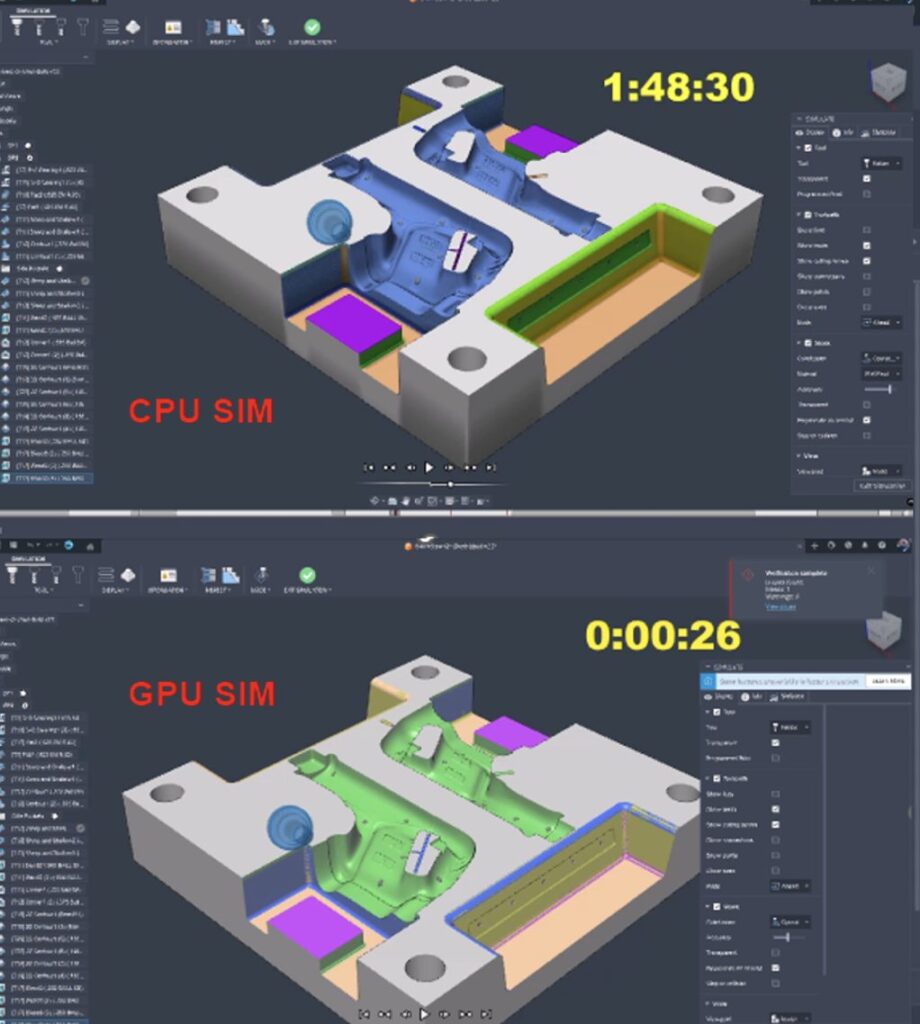
[Windows] GPU Based Stock Simulation
We are thrilled to announce a ground-breaking improvement in the manufacturing simulation space. In the September release, we are fully releasing GPU based stock simulation in the manufacturing environment.
This will massively speed up simulation calculation times, in some cases it cuts the time from hours to seconds.
Learn more about GPU Based Simulation
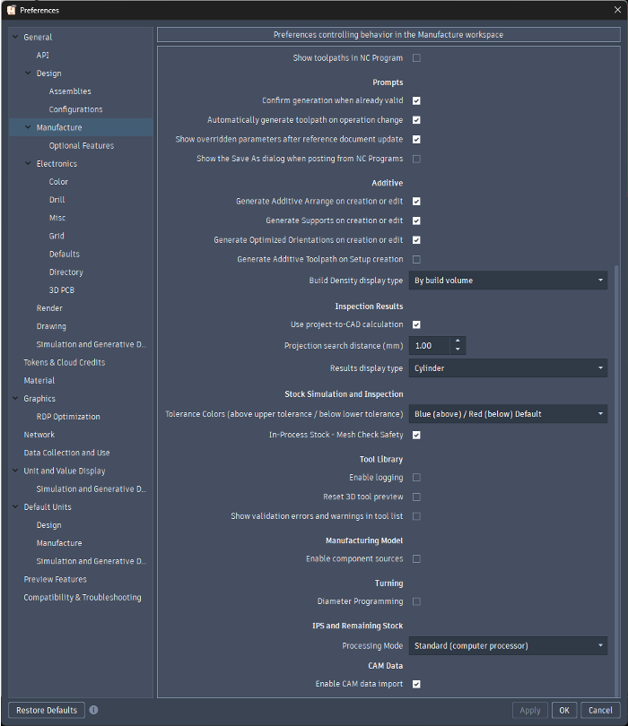
Option to Disable ‘Import CAM Data’ for Linked Designs
Fusion allows you to insert an external design into the current design to create an assembly. Originally any CAM data (Manufacturing setups or operations) in the linked design was not imported, so any toolpaths in the linked design were lost on import.
Last year we extended the capability to reuse CAM setups and operations from linked designs. The CAM import is optional but some users had already developed workflows based on the assumption that CAM setups and operations would not be imported from linked designs, and they never wanted to import the CAM data.
With this update we have provided Preference in the Manufacture Workspace that allows you to control ‘Enable CAM data import.’ This is enabled by default but can now be disabled.
Learn more about importing CAM data.
Machine Management Improvements
Starting in September, you can easily swap machines in your setups and NC programs, and remove them from your documents.
Learn more about machine management improvements.
Improved Performance with Manufacturing Selection Sets
We’ve enhanced the performance and usability of manufacturing selection sets- this is the latest part of an ongoing project to improve the selections for more complex operations with larger models.
You can create a manufacturing selection set to create groups of faces for reuse in geometry selections. Previously the selection performance slowed down significantly as the selection sets grew larger, and very large selections sets were sometimes split into multiple geometry selections, rather than remaining together as a single geometry selection. Now the response is faster and large selection sets will create single geometry selections.
Additional Threading Tool parameters
When defining a Milling > Thread type tool, users can now specify a Flat, Sharp or Radius Tip definition. This will allow our users to define their tools correctly and receive correct G-Code with a lot less trial and error.
Turning
New Trace Strategy
We’ve added a new Turning Trace strategy that enables you to turn complex shapes more easily. This feature allows the tool to follow the contour of your model, helping you achieve precise and intricate designs with greater efficiency
Learn more about the Turning Trace Strategy.
New Standard Definition Mode for Turning Thread
There is now a new “standard” thread definition method for turning thread strategies. This new method allows you to machine an industry standard thread to program a threading toolpath without manually having to enter thread definition parameters in the manufacturing space.
Additive Manufacturing
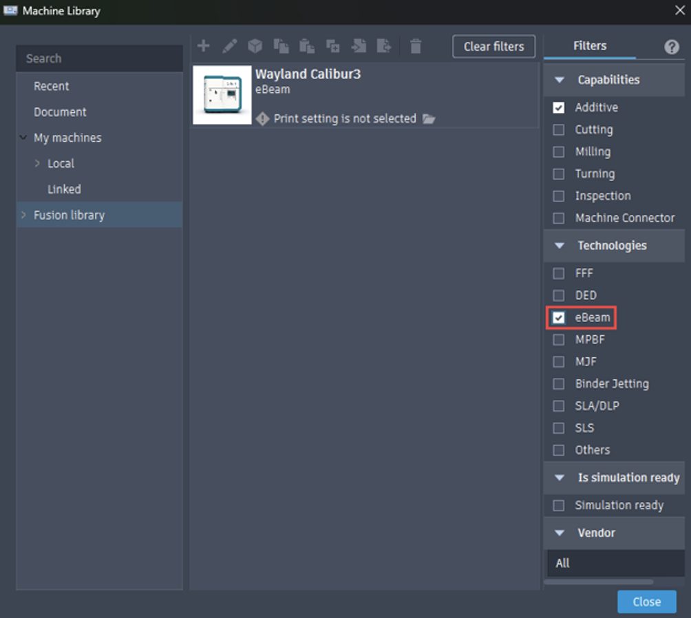
New eBeam (Manufacturing Extention)
We have added a new additive manufacturing technology for Fusion users: eBeam. Similar to Metal Powder Bed Fusion (MPBF), eBeam uses an electron beam instead of a laser to melt powder. With the release of this new additive technology, we have also introduced an eBeam machine, the Wayland Calibur3. To access this technology and machine, ensure you have the manufacturing extension enabled.
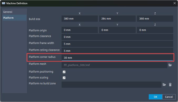
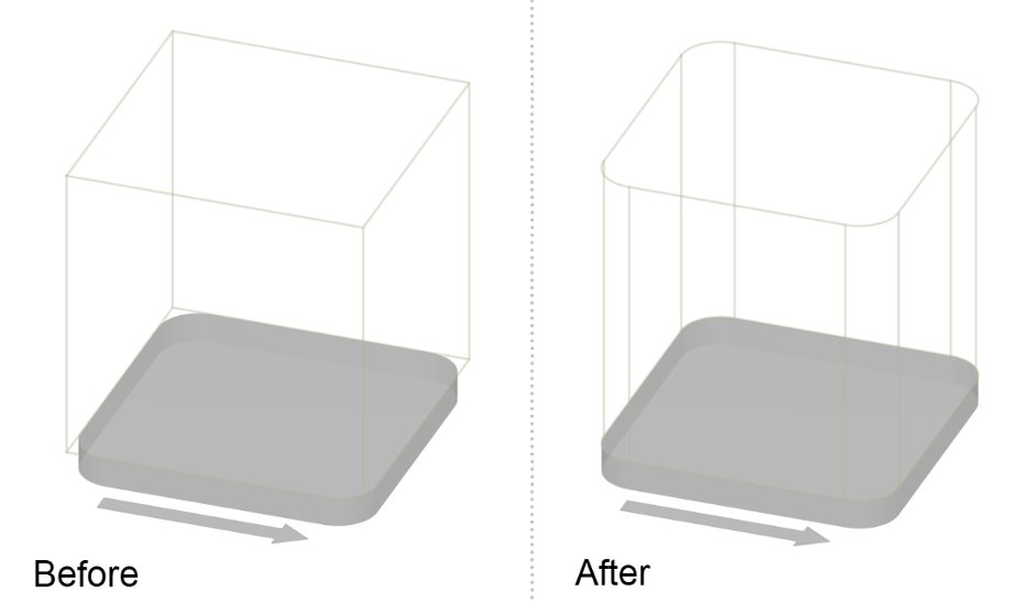
Additive Machines with Rounded Corners
We added the ability to create additive machines with rounded platform corners. You will find a new option named Platform corner radius in the Platform tab of the machine configuration. This option also enables the creation of additive machines with circular platforms by setting the platform corner radius to half the platform length.
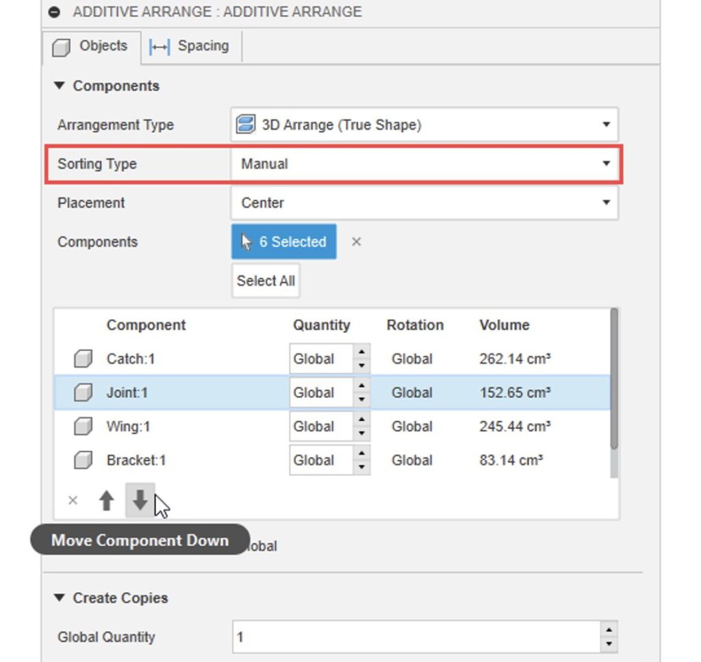
New Manual Sorting Type
We’ve introduced a new option called “Manual” to the Sorting Type (formerly known as Priority Type). This enhancement allows you to set the order in which components are arranged. Simply use the arrows to organize the components in the component table to your preference.
Learn how to Arrange Components for Additive Manufacturing.
2D Fill Build Volume Now Uses True Shape
Autodesk’s premium arrangement method is now being used for the 2D Fill build volume command. This will give better 2D nesting results and will better consider no build zones and machines with rounded build platforms.
Remove Component from Setup Command
The previous “Remove excess components” command allowed you to remove components from the setup that were outside of the build volume. We had a lot of positive feedback about this command, but also some feedback saying that it was too hidden (previously this command was only accessible by right-clicking on the setup). We took on this feedback and decided to redesign and improve the command, as well as adding it to the toolbar for visibility and easy access.
Additionally, you are now able to use the ‘Remove from setup’ command to individually select components that you wish to remove from the setup.
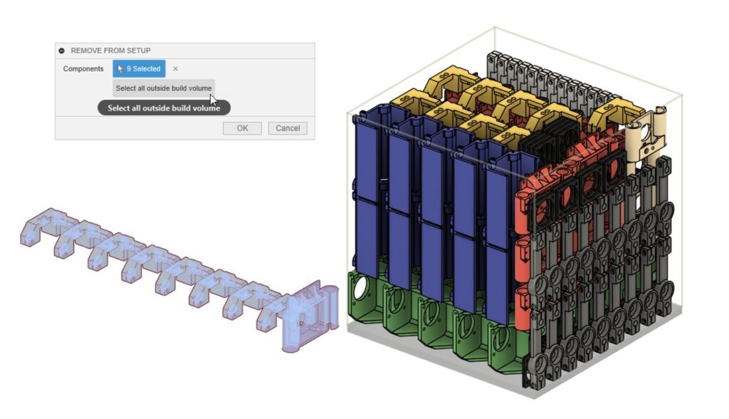
Learn how to remove Components from an Additive setup.
Post Processor and Machine Simulation
Looking for the latest post processors and machines updates? We released a ton of new updates and improvements to many of the open-source Post Processors and Machines we offer for free. Within the latest release you will find improvements to post processors including Generic Post Processors, Milling Post Processors, and Turning Post Processors. We also added new machines to our Machine Library, updated our Workholding library, and improved functionality around the Autodesk CAM Post Processor engine.
Learn what’s new for Post Processors and Machine Simulation this August.
API
New Arrange API
In this release, we are opening up the API to support Arrange functionality. This allows you to build Add Ins, and Scripts, to automate Arrange workflows and streamline the Design to Manufacturing process for Flat Components in an assembly. Note, Sheet Metal parts are not automatically flattened by Arrange.
You can find more information on functions and API calls in the Fusion API Reference Manual.
Insider Program
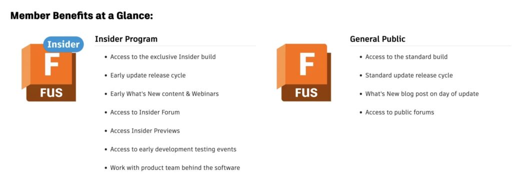
Do you want to engage more with the Autodesk community? Check out the Fusion Insider program to use exclusive previews, and test out the latest build before it’s released to the public?
As a member, you’ll gain inside knowledge of updates and a first look at new features. You’ll also be able to join exclusive events and try pre-release functionality. Plus, you can give feedback directly to the product teams.
Release Notes
But wait, that’s not all! To see more fixes, minor enhancements, and keep up with the latest check out our Release Notes for the full rundown on changes to Fusion and Fusion web client.