 Marti Deans
This post is also available in:
G‑code is the core programming language used to control CNC machines, defining how tools move and operate to manufacture parts accurately.
Elevate your design and manufacturing processes with Autodesk Fusion
You know what they say about fundamentals: learn them first, and you’ll remember them forever. The same holds true for CNC machine programming. Even as new manufacturing technologies unfold, the fundamentals for how parts are machined with a CNC program will stay with you forever.
In this article, we’ll be talking about the core component of every CNC program – G-code. G-code stands for “geometric code” and serves as the fundamental instruction set for CNC machines, guiding their movements and translating digital models into precise physical actions.
What Is G-code?
G-code is the programming language used to control CNC machines. It tells a machine where to move, how fast to move, when to start cutting, and which tools to use during a machining operation.
Every CNC machine relies on G-code to convert digital part designs into physical components. Whether you’re machining simple brackets or complex aerospace components, the machine ultimately follows G-code instructions to perform the work.
Is G-code still used in modern CNC manufacturing?
Yes. While modern CAM software automates much of the programming process, G-code remains the language that CNC machines use to execute machining operations.
Today’s programmers rarely write large CNC programs by hand. Instead, CAM software generates machine-ready G-code automatically from machining strategies, toolpaths, and machining parameters.
Understanding G-code remains valuable because it helps machinists troubleshoot issues, optimize jobs, and verify machining intent before running production parts.
G-code at a glance
Manufacturers all around the world use CNC programming to control a machine’s tools to produce parts. At the heart of this automated manufacturing process is a set of instructions, where each instruction is a specific command in the G-code program, that tells a CNC machine where – and how – to move. These instructions are called G-Code.

G-code was first established in the 1960s by the Electronics Industry Association (EIA). While the official language was documented as RS-274D, you’ll hear everyone refer to it as G-code. Why? Many of the words, or individual pieces of code, that make up this machine-based language start with the letter G.
While G-code is supposed to be a universal standard, you’ll find that many CNC machine companies have developed their own unique flavor. CNC machines follow specific G-code and M-code standards, but variations exist between brands and models. We’re all be eating ice cream at the end of the day, but a Haas might be strawberry flavored, and a Tormach might be chocolate flavored. Because of this difference in G-code flavors, it’s imperative to understand how your own machine uses G-code.
Do you need to know G-code to use CAM software?
Not necessarily. Modern CAM software allows machinists to create toolpaths visually without manually writing G-code.
Instead of programming every move by hand, users define:
- Tool selections
- Machining operations
- Cutting parameters
- Workholding setups
The CAM system then automatically generates the appropriate G-code for the target machine.
That said, understanding G-code fundamentals can make it easier to:
- Debug machining issues
- Validate tool motion
- Optimize cycle times
- Understand post processor output
Many CNC programmers learn machining strategy first and then develop deeper G-code knowledge over time.
Manual G-Code vs CAM-Generated G-Code
Historically, CNC programmers often wrote programs manually.
Today, most manufacturers use CAM software to generate G-code automatically.
| Manual G-Code Programming | CAM-Generated Programming |
|---|---|
| Code written line-by-line | Toolpaths generated visually |
| Time-intensive | Faster programming |
| Difficult to modify | Simple design revisions |
| Increased risk of mistakes | Built-in validation and simulation |
| Better for simple operations | Better for complex parts |
Manual programming is still useful for learning CNC fundamentals and handling simple machine operations. However, CAM software is generally preferred for production environments because it improves consistency, efficiency, and scalability.
Types of G-code
Why the difference in G-code flavors? It really comes down to the capabilities of each machine. Take one machine that can process a coordinate system rotation based on probe inputs. You’ll need a set of G-code commands that can enable or disable this rotation. Another machine without this adjustment capability won’t require that G-code. Certain G codes are unique to specific machine types or operations, so while many codes are standard, some are specialized for particular functions or equipment.
When in doubt, always refer to your CNC machine’s documentation as you work through the rest of this article. We’ll be walking through the basics, but you never know if your machine might have taken a slightly different path to the same end destination. Consulting the G code list for your specific machine is essential to avoid errors.
G-code blocks
The G-code standard was published back in the days when machines had small amounts of memory. Because of this memory limitation, G-code is an extremely compact and concise language that might almost seem archaic at first glance. Take, for example, this line of code:
G01 X1 Y1 F20 T01 M03 S500
In this single line, we’re giving the machine a series of instructions:
- G01 – Perform a linear feed move
- X1/Y1 – Move to these X and Y coordinates
- F20 – Move at a feed rate of 20
- T01 – Use Tool 1 to get the job done
- M03 – Turn the spindle on
- S500 – Set a spindle speed of 500
Multiple lines of G-code like these combine to form a complete CNC program. Your CNC machine will then read the code one line at a time from left to right and top to bottom, like reading a book. Each set of instructions is on a separate line or a block.
How does Fusion generate G-code?
Fusion automatically converts toolpaths into machine-ready G-code using post processors. Rather than writing code manually, users create machining operations such as:
- Facing
- Adaptive clearing
- Pocketing
- Drilling
- Contouring
Fusion then translates those operations into G-code that matches the specific CNC machine and controller being used.
Fusion includes an extensive library of post processors, making it easier to generate compatible code for a wide range of machines while maintaining a consistent programming workflow.
G-code programs
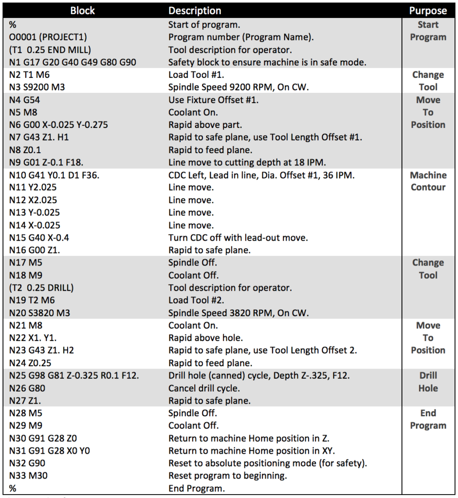
The goal of every G-code program is to produce parts in the safest and most efficient way possible. To achieve this, you’ll typically find G-code blocks arranged in a particular order like this:
- Start the CNC program.
- Load the required tool.
- Turn the spindle on.
- Turn the coolant on.
- Move to a position above a part.
- Start the machining process.
- Turn the coolant off.
- Turn the spindle off.
- Move away from the part to a safe location.
- End the CNC program.
Each step in the G-code program represents a specific function that the CNC machine executes, such as starting the spindle or moving to a safe location.
This flow is a simple program using only one tool for one operation. In practice, you will typically rinse and repeat steps 2 through 9. For example, the G-code program below encompasses all of the code blocks above with repeating sections where needed:
Modals and address codes
Like other programming languages, G-code can repeat an action indefinitely until stopped. This looping process uses modal code, which acts until you either turn it off or modify it with another modal code. For example, M03 is a modal code that will run a spindle indefinitely until you tell it to stop with M05. Now, wait a second. That word (remember: a word is a little piece of code) didn’t start with a G, but it’s still G-code. Words that start with an M are machine codes—M-code stands for “machine code”—and they control non-movement functions of the CNC machine, such as loading programs, pausing, and managing coolant flow. I’ll list some common ones in the next section, but you can find a list of your machine’s M-codes in its documentation.
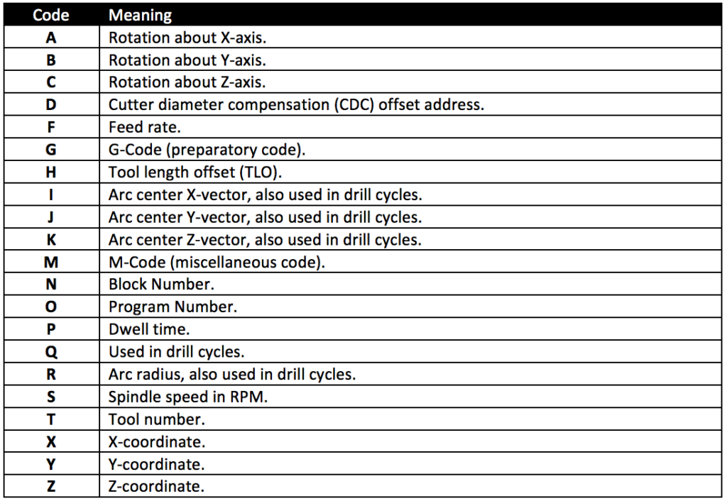
G-code also includes a complete list of address codes. You can think of these as the dictionary for G-code that defines particular behaviors. Address codes begin with the letter designation, like G, and then with a set of numbers. For example, X2 defines an X-coordinate address code, where 2 is the value on the X-axis to move the machine to.
The complete list of address codes includes:
Several special character codes can be added to a G-code program. These are typically used to start a program, comment out text, or ignore characters and include:
- % Begins or ends a CNC program
- () Defines a comment written by a CNC operator; occasionally, these must be in all caps
- / Ignores all characters that come after the slash
- ; Determines when a block of code ends, not shown in a text editor
G-codes & M-codes explained
G & M-codes will make up the bulk of your CNC program. Codes that begin with G prepare your machine to perform a specific type of motion. These commands control the tool movements required for machining operations. G-code is used to control various types of machine tool, including mills and lathes. The most common G codes that you’ll encounter time and time again in every CNC program include:
G0 – Rapid move
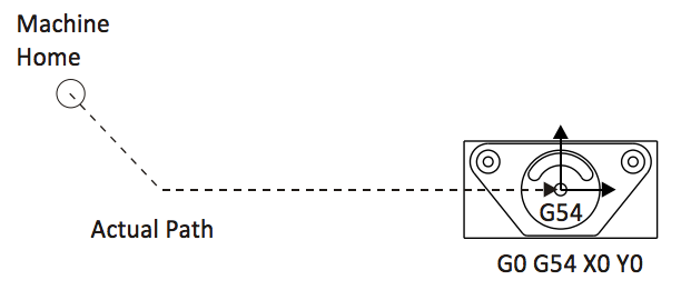
This code tells a machine to move as fast as possible to a specified coordinate position. G0 will move the machine axis by axis, meaning that it will first move along both axes and finish the move on whichever axis is not in positions. You can see an example of this motion in the image below:
G1 – Linear move
This code tells a machine to move in a straight line to a coordinate position with a defined feed rate. For example, G1 X1 Y1 F32 will move the machine to coordinates X1, Y1, at a feed rate of 32. G1 is commonly used on a mill for cutting material along a straight path.
G2, G3 – Clockwise arc, counter-clockwise arc
These codes tell the machine to move in an arc to a coordinate destination. G2 moves the tool in a clockwise direction, while G3 moves it in a counterclockwise direction. Both are used for cutting material along curved paths. Two additional coordinates, I and J, define the arc’s central location as shown below:

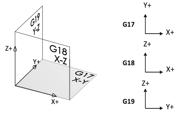
G17, G18, G19 – Plane Designations
These codes define what plane an arc will be machined on. By default, your CNC machine will use G17, which is the XY plane. The other two planes are shown in the image below:
G40, G41, G42 – Cutter Diameter Compensation
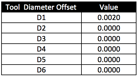
These codes define the cutter diameter compensation, or CDC, which allows a CNC machine to position its tool to the left or right of a defined path. A D-register stores the offset for each tool.
G43 – Tool Length Compensation
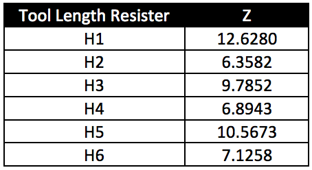
This code defines the length of individual tools using a Z-axis height. This allows the CNC machine to understand where the tip of a tool is in relation to the piece it is working on. A register defines the tool length compensations, where H is the tool length offset and Z is the tool’s length.
G54 – Work Offset
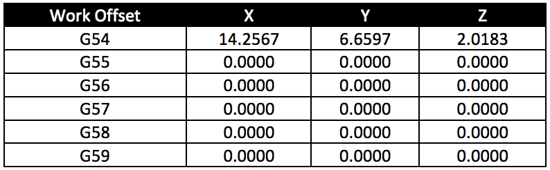
This code is to define a fixture offset, which determines the distance from a machine’s internal coordinates to the datum on a workpiece. In the table below, only G54 has an offset definition. However, you can program multiple offsets if a job requires machining multiple parts at once.
M-codes
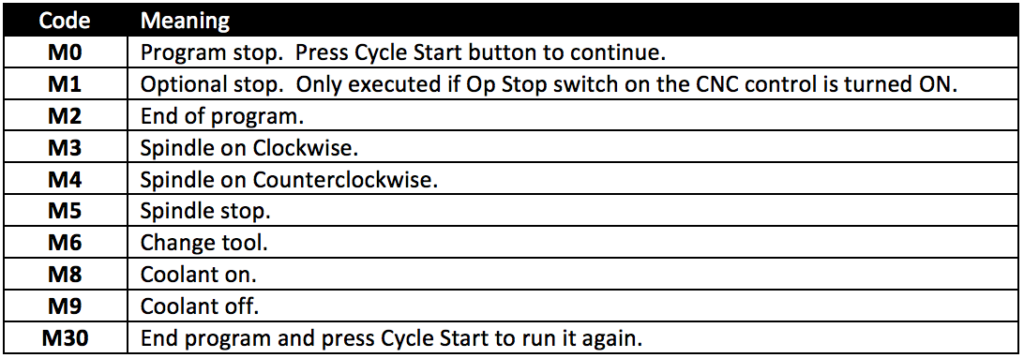
M codes are machine codes that might differ between CNC machines. These codes control functions on your CNC machine like coolant and spindle directions. Some of the most common M-codes include:
Common G-Code Mistakes
Even experienced CNC programmers occasionally encounter issues caused by programming errors or machine configuration problems. Common mistakes include:
Incorrect work offsets
Improperly configured work offsets can cause tools to machine in unexpected locations.
Incorrect tool length offsets
Invalid tool length values can result in poor cuts, collisions, or scrap parts.
Feed and speed errors
Overly aggressive feeds and speeds can reduce tool life and compromise surface finish.
Post processor mismatch
Generating code for the wrong machine controller can create unexpected machine behavior.
Running unverified programs
Programs should always be reviewed and simulated before machining production parts.
Using CAM software with simulation capabilities can help identify many of these issues before code reaches the machine.
Canned cycles in G-code
The last aspect of G-code to touch on is canned cycles. These are similar to methods or functions in computer programming. They allow you to perform a complicated action in only a few lines of code without having to type out all of the details.
Canned cycles include not only drilling cycles but also the boring cycle, which automates boring operations. A boring cycle streamlines the process of creating internal holes or bores by entering all parameters into a single command, making machining more efficient and precise.
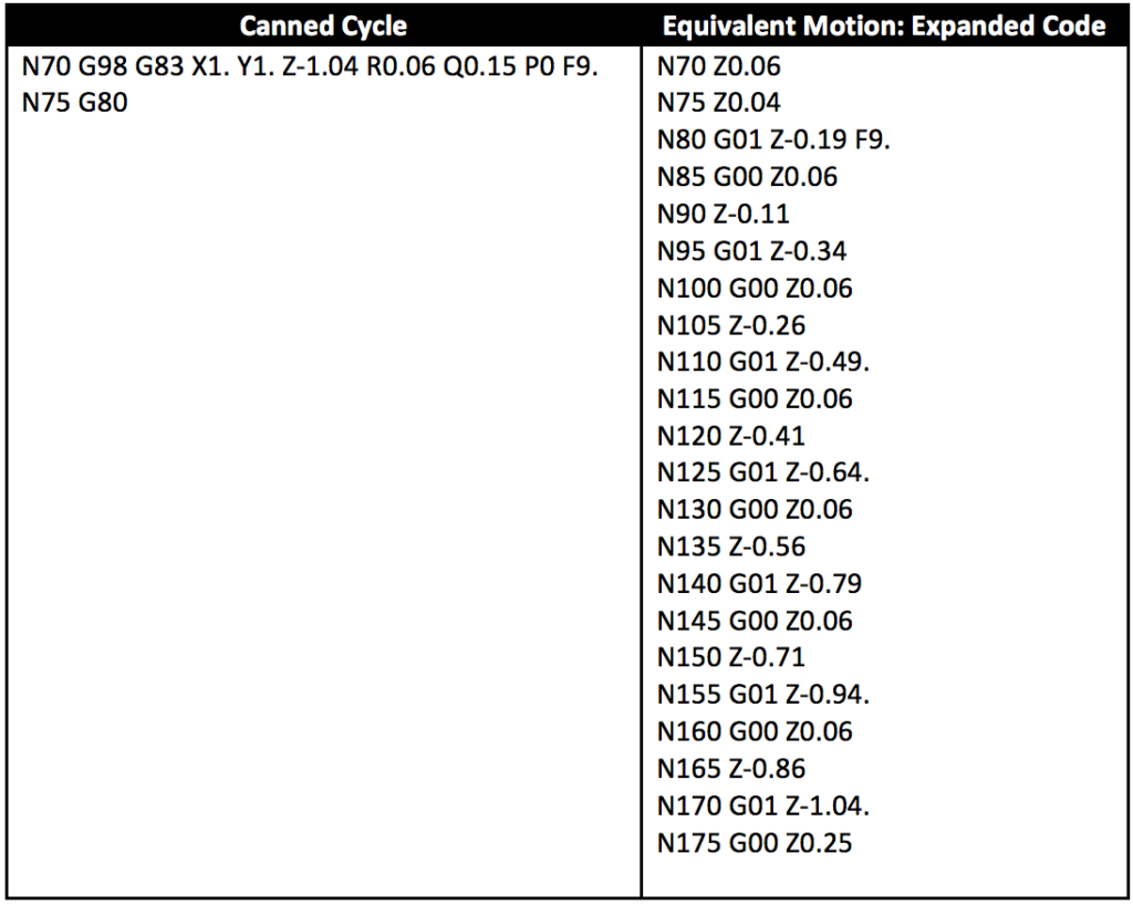
Take, for example, the canned cycle below. Here we are telling the CNC tool to create a hole with a peck drill in only two lines of code on the left. This same action takes over 20 lines of regular G-code.
Common drill cycles
G81 – Simple Drill Cycle
Before programming any drill cycle, it is essential to establish a precise reference point and define the work coordinate system. Setting the reference point ensures the CNC machine knows the exact starting location for drilling, while the work coordinate system provides a consistent framework for accurate hole placement and tool paths.
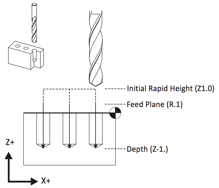
This cycle will make a hole by plunging to a specific Z-axis coordinate and then retracting. Programming this cycle requires a depth, feed rate, XY coordinates, and plane to drill on.
G83 – Peck Drill
This cycle is for quickly drilling deep holes. A tool will first drill a defined distance and then retract, which clears any material out of the hole and allows coolant to flush away chips. This cycle’s simplest implementation requires an initial height, feed plane, peck increment, and depth.
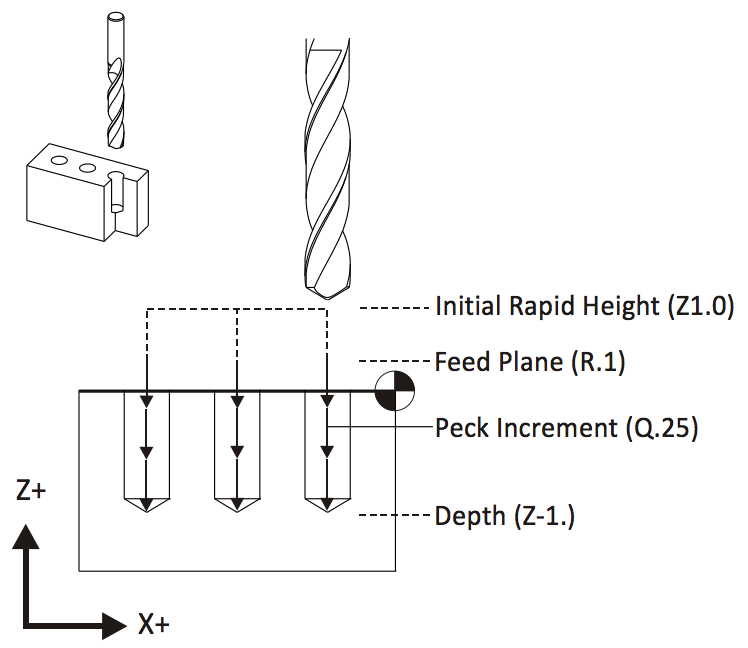
G98 – Return to Initial Rapid Height
This cycle will retract a tool to a clearance plane between holes, which helps to avoid clamps. Programming this cycle requires an initial height and feed plane to drill on.

Coordinate system and movement
A solid understanding of the coordinate system is essential for anyone working with CNC machines. CNC machining relies on a Cartesian coordinate system, where the X, Y, and Z axes define the movement and position of the cutting tool relative to the workpiece. The X-axis typically controls horizontal movement, the Y-axis manages vertical movement, and the Z-axis determines the depth of the cut. This three-dimensional framework allows CNC machines to follow precise tool paths, ensuring accurate and repeatable machining operations.
CNC programmers use G code commands to instruct the machine on how to move the cutting tool. For example, G00 is used for rapid movement, quickly positioning the tool to a specific location without engaging the material, while G01 enables linear interpolation, guiding the tool in a straight line at a controlled feed rate for cutting. Linear interpolation is particularly valuable for creating smooth, accurate lines and curves, which are essential for complex operations and intricate part geometries. By mastering the coordinate system and movement commands, CNC programmers can design efficient tool paths that maximize precision and productivity throughout the machining process.
Cutter compensation and tooling
Cutter compensation is essential in CNC machining as it allows the machine to adjust the tool path based on the actual size and shape of the cutting tool. This ensures that the final part meets the intended dimensions, even if there are slight variations due to tool diameter or wear. G code programming enables CNC programmers to set cutter compensation, allowing the machine to automatically offset the tool path as required, minimizing errors and material waste.
Selecting the appropriate cutting tools is equally crucial for achieving optimal results. Various types of cutting tools are designed for different materials and machining operations, from end mills for milling to drills for creating holes. CNC programmers must consider factors such as material hardness, desired surface finish, cutting speed, and feed rate when choosing these tools. M codes, which refer to miscellaneous codes, control auxiliary functions like tool changes and spindle speed adjustments, ensuring smooth transitions between different tools and operations. By effectively using G code and M code programming, CNC machines can perform efficient tool changes, maintain optimal spindle speeds, and improve overall machining efficiency, resulting in high-quality, precise components.
Safety considerations and best practices
Safety is crucial in CNC machining due to the high speeds and forces involved, which can present significant risks if not properly managed. CNC programmers and operators must prioritize best practices to ensure a safe machining process, starting with thorough machine setup and selecting the appropriate cutting tools for each job. Keeping a close watch on the machining process can help identify potential issues early, such as unusual tool wear or unexpected material behavior.
G code programs can be written to incorporate safety features, including limiting feed rates and spindle speeds to prevent overloading the machine or causing tool breakage. Modern CNC controls come with safety interlocks and error detection systems that can automatically stop the machine if a problem is detected. Additionally, CAD/CAM software can be used to simulate and verify the machining process before running the actual program, helping to identify and eliminate potential errors and thus reduce the risk of accidents. By following safety guidelines and utilizing advanced software tools, CNC programmers can create a safer and more reliable machining environment.
Troubleshooting and error handling
Even with meticulous planning, errors can still occur during CNC machining due to programming mistakes, equipment malfunctions, or material inconsistencies. Effective troubleshooting and error handling are critical skills for CNC programmers. When issues arise, analyzing error messages from the CNC controls and reviewing the G code program can help identify the problem’s source. Adjusting the code, such as correcting tool paths or modifying auxiliary functions controlled by M codes, often resolves these issues.
M codes manage essential auxiliary functions like spindle speed control and tool changes, and problems in these areas are frequently linked to incorrect programming or mechanical faults. CAD/CAM software allows programmers to simulate the machining process and detect potential errors before they reach the shop floor, saving time and reducing material waste. By remaining vigilant and utilizing the right tools and software, CNC programmers can efficiently troubleshoot and resolve errors, ensuring the machining process runs smoothly.
Optimization and efficiency
Maximizing efficiency is a crucial goal in CNC machining, as it significantly affects productivity and cost-effectiveness. CNC programmers can enhance CNC programs by minimizing unnecessary tool changes, selecting the most efficient tool paths, and optimizing feed rates and spindle speeds for each operation. G code programming allows the specification of these parameters, ensuring each machining step is as efficient as possible.
CAM software is essential for analyzing and optimizing the machining process, allowing programmers to simulate various strategies and select the best approach for the job. Utilizing canned cycles for repetitive operations, such as drilling or boring, can further streamline the process and reduce programming time. Choosing the appropriate CNC machine and cutting tools for the specific material and operation also boosts efficiency. By continuously refining their programming techniques and harnessing advanced software tools, CNC programmers can reduce production time, minimize waste, and consistently deliver high-quality machined parts.
How CAM software reduces manual CNC programming
Understanding G-code is valuable. Spending hours manually writing it is often not. Modern CAM software helps manufacturers automate much of the programming process by generating machine-ready code directly from CAD models. Benefits include:
- Faster setup: Toolpaths can be created visually rather than programmed line-by-line.
- Easier design revisions: When a design changes, toolpaths and G-code can be regenerated automatically.
- Fewer programming errors: Built-in simulation and verification help identify issues before machining begins.
- Simplified post processing: Machine-specific G-code can be generated automatically using post processors.
- Improved standardization: Programming workflows become more consistent across users, parts, and machines.
For many manufacturers, the greatest value of CAM software isn’t eliminating G-code entirely, it’s reducing repetitive programming tasks so machinists can focus on part quality, throughput, and process improvement.
From learning G-code to programming parts
Understanding G-code remains one of the most valuable skills in CNC manufacturing. It helps machinists understand machine behavior, troubleshoot issues, and validate machining operations.
However, modern manufacturers rarely rely on manual G-code programming alone.
Today’s CAM systems automate toolpath creation, simulation, and G-code generation, allowing programmers to move from CAD model to production-ready code significantly faster.
Whether you’re learning CNC programming for the first time or looking to improve programming efficiency, combining strong G-code fundamentals with modern CAM workflows provides the best path forward.
Generate your first CNC toolpath in Fusion
Ready to move beyond manual programming? With Fusion, you can:
- Create CNC toolpaths visually
- Simulate machining operations
- Automatically generate machine-ready G-code
- Use built-in post processors
- Reduce programming time and improve consistency
Start a free 30-day Fusion trial and generate your first CNC toolpath today.