Join us as we highlight standout moments in Fusion from the first half of 2025!
Table of Contents
We’re over halfway through the year and we’ve already introduced three major updates so far. During this time, we’ve made several changes to simplify and improve your workflows. We’ve added AI-powered tools like AutoConstrain, made improvements to assemblies, introduced new graphics options, upgraded tools for working with electronics, added new manufacturing toolpaths, and so much more.
Let’s do a quick recap of our favorite updates from this year.
Usability
New Graphics Options Presets
We introduced three fantastic new presets to make it easier for you to tailor your experience: ‘Custom,’ ‘Performance,’ and ‘Quality.’ You can access these from both the canvas toolbar and the Preferences dialog, where all graphics-related settings are now neatly consolidated.
- Performance: Disables effects for ultra-smooth navigation targeting 60+ FPS, perfect for everyday workflows.
- Quality: Activates all effects for stunning visuals, ideal for screenshots and design presentations.
- Custom: Combine performance and quality settings to meet your needs.
Release Notes for Fusion and Fusion Web Client
Back in January we announced the addition of detailed release notes to the Fusion Help section. This means you can stay informed about new features, improvements, and fixes as they are released, ensuring you always have the most up-to-date information at your fingertips.
Data Management
Rolling Out a New Collaborative Data Experience
We know data management is at the forefront of everything you do, and we are actively working to continuously improve your experience. Earlier this year, we began to roll out a new Collaborative Data experience, focused on keeping your teams more connected than ever before. Want to dive deeper? Check out this video for all the details!
Design
AI-Powered AutoConstrain
As we embarked on the exciting journey of 2025, we kicked things off with the revolutionary AI-powered AutoConstrain in Fusion. Imagine a tool that automatically identifies and applies sketch constraints and dimensions to unconstrained sketch geometry. Sounds like magic? It’s real! Nestled under the new Automate tab in the Sketch environment, AutoConstrain works diligently to ensure your sketches are robust and fully constrained, sparing you the tedious task of manual adjustments.
Curious about how AutoConstrain can transform your workflow? Dive deeper and discover more possibilities!
Fastener Auto Length
Next up, we increased automation when placing fasteners into your designs straight from the fastener library. This means fasteners that intuitively calculate the appropriate length based on surrounding feature geometry and engineering standards. No more guesswork! The fasteners will help ensure the perfect fit for hole types, and if you wish, you can modify the default calculated clearance value before placement.
Enhanced Surface Offset Command
Moving forward, our Surface Offset command received a fantastic upgrade, bringing you enhanced flexibility with every design you create. Similar to the shell command, you are now able to choose between two types when using the surface offset command. You can either have a sharp offset as before, or choose a rounded offset. This allows you to apply the type of offset that best suits your design vision.
Enhanced DXF Export Control
On top of all of those amazing enhancements you now have greater control over DXF exports from Sketch and Flat Pattern in the Sheet Metal workspace.
Simply select the units for DXF export according to your requirements, ensuring compatibility with different standards and preferences. Additionally, you have the option to choose specific entities for export, such as projected geometry, construction geometry, and points in a Sketch, as well as center lines and extent lines in a flat pattern.
New Design Samples
Starting in January and throughout the year we have been overhauling the Fusion design samples with new and inspiring designs. One major update will be the inclusion of assemblies with independent distributed designs. We have also enabled the ability to copy samples directly to your hub from the data panel or home tab, using the context menu, for practice, learning and general exploration. These designs are accessible from either the data panel or home tab.
Assembly Improvements
Enable History on Import
Let’s revisit one of the subtle yet impactful enhancements we released this year. Users have always had the ability to set a preference for whether new designs should begin as parametric (capturing design history) or direct (without capturing design history). By default, this preference was set to Parametric, meaning all new designs came with the timeline for history enabled.
However, importing non-native CAD formats like STEP, SAT, STL, etc., used to bypass this preference and bring in designs as direct models, without capturing their history. This quirk often left you without the much-needed timeline for adjustments and revisions.
We addressed this concern by ensuring non-native CAD format imports now respect your preference setting. This enhancement provided full control over your design flow, making your experience even more intuitive and tailored to your needs.
New Assembly Relationships Nodes Grouping in Browser
We’ve also streamlined your workflow by grouping various assembly relationship nodes, like joints and tangent relationships, into one convenient folder named “Relationships” in the browser. This makes keeping track of your assembly relationships a breeze.
Drawings
AI–Powered Fastener Detection
Earlier this year, we introduced AI-powered Fastener Detection for Drawing Automation. This groundbreaking feature utilizes artificial intelligence to detect and omit fasteners during the automatic drawing creation process.
As part of this feature, a ‘Detect and Omit Fasteners’ checkbox option has been added in Automation settings tab of Document settings dialog.
Note: this option is off by default.
Drawing Sketch Constraints
Precision in your designs is crucial, and we’ve made significant strides with Drawing Sketch Constraints. This feature allows you to add constraints to your sketches and title block entities, ensuring more accurate and detailed designs.
New Crop View
We also unveiled the New Crop View feature within the Design environment. This is particularly useful when a specific area needs to be shown in the view.
Electronics
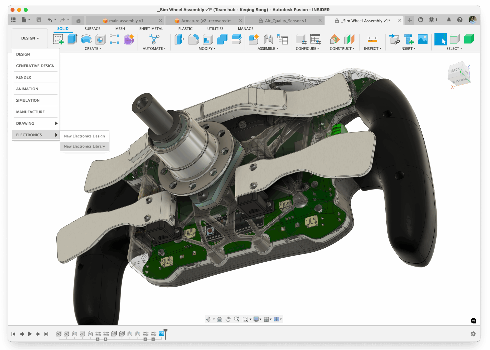
New “ELECTRONICS” Option in Workspace Switcher
This year, we have made it easier to find and use our electronics functionality with the introduction of “ELECTRONICS” in the Workspace Switcher in Fusion.
Create In Place, Create External PCB Document in Assembly Context
A new ‘Create In Place’ feature for PCB has arrived, revolutionizing the way you design PCBs within a design context. This innovative feature offers you a streamlined workflow path to author PCB data using familiar Fusion skills, mirroring the process of creating any other mechanical component. With ‘Create In Place,’ you can manage a single source for the board outline, ensuring data consistency without circular dependencies.
Now you create a PCB like you would any other mechanical component allowing you to stay within the assembly. Mechanical driven constraint data is now respected and the reference geometry concept has been introduced to 3D PCB. This enhancement provides a more Fusion-centric approach, streamlining your PCB design experience while maintaining the integrity of your assembly contexts.
Electronics Drawings Support for Reference Designators in PCB and Layer Stack Table
Previously, when documenting Electronics within Fusion Drawings you had to copy and paste screenshots of Electronics documentation. This often resulted in outdated and cumbersome data management. With this enhancement we are changing the documentation process by integrating Fusion Electronics documentation workflows directly into the drawings workspace, creating a unified and purpose-built environment.
Fusion Electronics now supports PCB Drawing creation where ‘Reference Designators’ are properly shown for almost all views in Fusion Drawings, including Base Views, Isometric Views, Detailed Views, and Breakout Views. Additionally, you can now generate appropriate ‘Layer Stack’ information in Fusion Electronics drawings, helping you enable efficient energy distribution, minimize interference, and support high-speed signals.
Learn more about Electronics Drawings.
New Native Teardrop Support
Earlier we announced the addition of native capability to support teardrops in Fusion Electronics, driven by Design Rules. Before this, teardrops had to be created using ULPs and were not native design assets. This meant you had to manually avoid creating design rules and manufacturing errors and were forced to resolve these issues manually.
Using our Design Rules architecture introduced last year, we now have design rule constraint-driven Teardrop generation. Teardrops can now be automatically generated and will always adhere to design and manufacturing rules. You can turn teardrops Off or On as needed through the Inspector or Properties, giving you full control over their application. We now support teardrops for Via, PTH, SMD Pad, and Trace-to-Trace (Taper) connections, enhancing the robustness of your designs.
Simulation
New Study Materials UI for Injection Molding Simulation
Simulation > Injection Molding Simulation Study > Study Materials
We have been working on a new user experience for the Study Materials Selection dialog for Injection Molding Simulation study along with moving the injection molding thermoplastics material database to the Autodesk Platform backend.
You will see this experience when you go to select a material for your Injection Molding Study. The new UI has almost all the existing capabilities like:
- List View
- Add/Remove and Sort Columns
- Search and Filter
- Favorites and Recents
- Material Properties Details View
- Search in Material Properties
We also added capabilities such as:
- Search Improvements: Improved search bar where you can quickly type the keywords you wish to search and the system will account for all of the keywords individually.
- Panel View: See key properties of a selected material in a side panel in the Study Materials UI. Click the “+” sign to expand and view property details for the respective categories.
Manufacturing
Collision Avoidance for Drilling Toolpaths
Drilling toolpaths can now avoid shaft and holder collisions on cutting moves, with associated shaft and holder clearances. Tick the Shaft/Holder tick box on the tool tab and choose from two options on the drop down:
- Fail on collision – if a collision is found the toolpath calculation will fail and return an error
- Skip colliding holes – holes that involve a collision will be removed entirely from the toolpath
Link moves between holes are now gouge checked by default and there is a new linking tab with options for how to avoid gouges (and collisions if Shaft/Holder avoidance is active) on these moves.
The Retraction policy drop down offers two options (remember that each hole can have its own retract height/plane):
- Avoid collisions – link moves will lift over obstacles to avoid gouges with the tool cutting component and collisions with shaft and holder if shaft/holder tick-box is ticked on the first tab.
- Preserve cycles – the toolpath will not avoid gouges and collisions, in order to preserve cycle output.
A warning message will be issued when they are detected. Gouge (collision between cutter and model) checking can be enabled or disabled on cutting moves using the Use Tool tickbox in the Shaft & Holder section of the Tool tab.
Reuse Tool Orientation
Similar to Geometry Selections, you are now able to see an existing Tool Orientation when you expand a machining operation. To reuse the Tool Orientation from an existing operation, first create or edit the new operation and set its Tool Orientation to ‘Coordinate System.’ Then select the required Tool Orientation from the expanded view of the existing machining operation.
Improved Heights UI
Listening to the feedback received about the changes to the Heights UI, we brought back the single-criteria options restoring them to be the system defaults; options such as Stock Top, Model Bottom etc. We also added new single-criteria options to define Heights relative to the Fixture Top or Fixture Bottom (or Fixture Outer Diameter and Fixture Inner Diameter for radial Heights).
We realize that the multi-criteria options were too restrictive, only considering the tops of things or the bottoms of things; sometimes you need to compare the top of one thing with the bottom of others. So, we’ve made those options more flexible. And renamed them too, to convey their meaning more simply.
Turning
Turning Profile Roughing and Finishing: New Parameter for Multiple Region Machining
We introduced a new parameter for turning profile roughing and finishing toolpaths. This enhancement allows you to choose whether to machine multiple disconnected OD/ID and face regions on your model, ensuring more effective and customizable machining operations.
Turning: Enhanced Control for Approach and Retract X Coordinates
Additionally, you can now specify turning toolpaths to start or end at the X coordinates of the start and end points respectively.
Additive Manufacturing
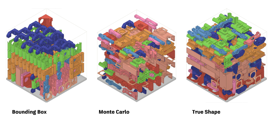
New 3D Nesting Method
After creating an Additive Setup with an SLS or MJF 3D printer, you can use the Additive Arrange command and select the new arrangement type “3D Arrange (true shape)”. This new voxel based arrangement method allows you to control the part quantity, packing priority as well as part rotations during the packing process. Builds 3D packed using this method often result in a higher packing density and create part placements which consider no build zones specific to certain 3D printers.
New Part Placement Functionality for Additive Arrange
We added a new “Placement” option to the 2D Arrange (True Shape), 3D Arrange (True Shape) and 3D Arrange (Bounding Box) arrangement.
If you select ‘Center’, the first arranged component will be placed in the center of the build platform. The arrangement type you selected will prioritize placing the subsequent parts around the initial part in a circular fashion.
If you select ‘Lower Left Corner’, your first arranged component will be placed close to the bottom left corner of the build volume. The subsequent parts will be placed along the X axis first, Y axis next and finally the Z axis of your available build volume.
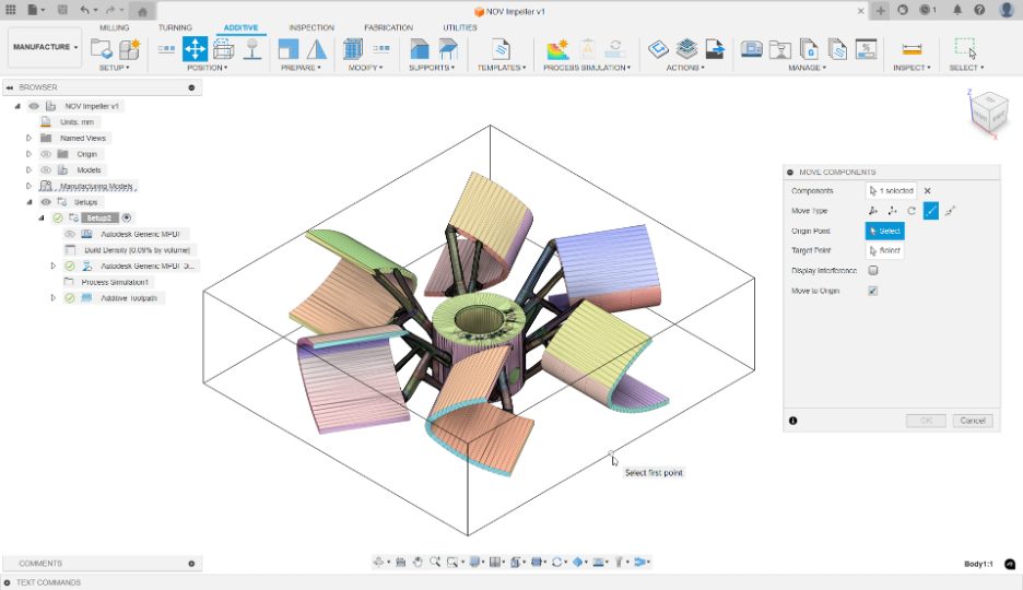
Improved Move Command
The Move command within the Manufacture workspace has been improved to match the move command located in the Design workspace. This change includes all the movement types (free move, translate, rotate, point to point and point to position) the move command in the Design workspace offers. The improved Move command now allows you to set a new pivot position for your selected components. You also have the option to display any potential collisions between components that may cause interference.
Shaping Tomorrow
As we journey through 2025, we’re thrilled with the depth of enhancements and innovations we’ve introduced in Fusion. Each update brings us closer to a future where your design and manufacturing processes are not only simplified but also empowered by intelligent tools and streamlined functionalities. We can’t wait to see how these updates transform your projects and inspire your creativity. Stay connected for more innovations as we continue to evolve Fusion together!
Be at the Forefront of Fusion
Do you want to engage more with the Autodesk community? Check out the Fusion Insider program to use exclusive previews, and test out the latest build before it’s released to the public?
As a member, you’ll gain inside knowledge of updates and a first look at new features. You’ll also be able to join exclusive events and try pre-release functionality. Plus, you can give feedback directly to the product teams.