Learn how to speed up thermo-mechanical additive process simulation by an order of magnitude.
Elevate your design and manufacturing processes with Autodesk Fusion
Additive process simulation uses first principle physics to predict how a metal 3D printing process behaves. It outputs the full temperature history of a selective melting process, as well as the deformation that those temperatures cause at each time during and after printing. Autodesk Fusion and Autodesk Netfabb have included a state of the art additive process simulation kernel for several years now.
The printed geometries are represented by tiny volumetric cube elements that form the desired shape. The complexity and the number of those voxels determine the runtime and memory requirements of the simulation. In this article, we describe two of the newest research developments in this technology – which have a dramatic effect on a reduction of both.
The first is user-controllable feature-aware meshing. It takes additional regional information for a design and improves the accuracy of the simulation algorithm in zones that the user cares about most.
The second is PRM generation. It expands the range of additive manufacturing machines that can be simulated directly within Fusion.
User-controllable feature-aware meshing
1. The challenge
Additive process simulation can be computationally intensive, especially for large or complex geometries.
In the past, Autodesk has implemented several smart strategies to improve performance – such as adaptive layer-wise meshing and multi-scale powder bed simulation. However, one key bottleneck has persisted – uniform mesh settings across the entire build plate.
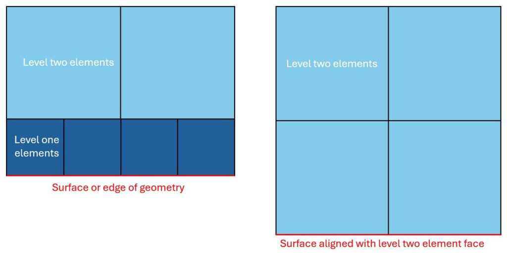
Thin walls and intricate features demand fine resolution with many small elements. This refinement, however, unnecessarily increases node and element counts in bulkier regions. While octree-based adaptive meshes can coarsen interior sections, surface regions still require refinement, adding more nodes and slowing performance. Even planar, axis-aligned surfaces can trigger unnecessary refinement depending on how they align with the super-element grid (see Figure 1).
2. Feature-aware meshing
Feature-aware meshing introduces flexible mesh control, allowing different mesh settings in different regions—either per body or within a single body. For example, the thin vanes of a heat exchanger can retain fine mesh resolution, while the surrounding bulky geometry can be coarsened by one or two levels.
This selective coarsening reduces the total number of nodes and elements while maintaining high accuracy where it matters most. The result is significantly lower computation time and memory usage, enabling simulations of larger, more complex geometries even on systems with limited RAM.
3. Simulation example
Feature-aware meshing is implemented using discrete field information, which prescribes different coarsening levels throughout the volume.
- A blue value indicates the finest mesh.
- Yellow merges 2×2×2 fine elements.
- Red merges 4×4×4 fine elements, and so on.
Although only two or three coarsening zones are typically needed, the number of zones can be extended up to the total number of adaptivity generations.
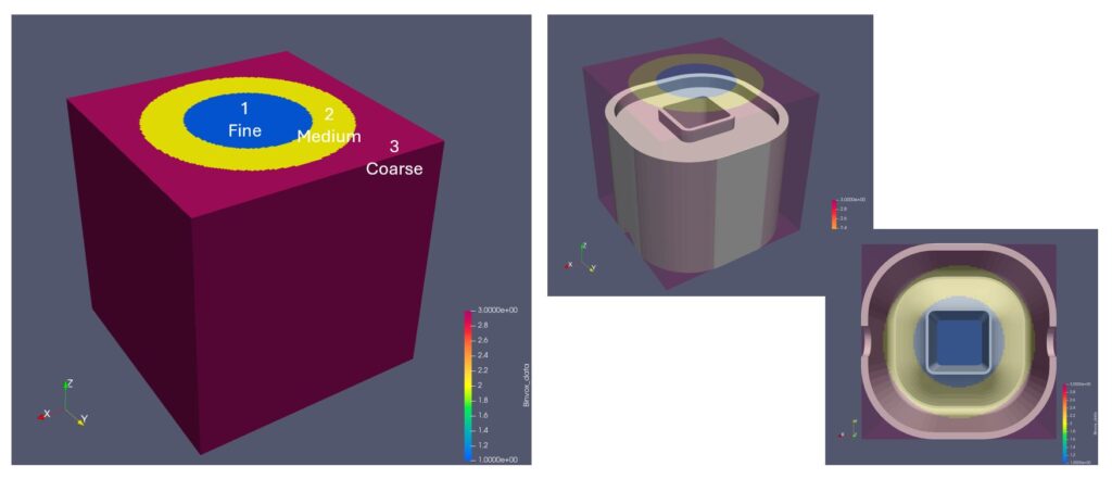
An example of coarsening level zones is shown in Figure 2. The canonical geometry used in this example consists of a very thin 0.415 mm inner ring and a thicker outer ring which join at the top of a swept arch profile. In this example, a fine mesh is used for the inner ring with two additional levels of coarsening towards the perimeter of the geometry. Note that the coarsening levels vary continuously. There is never a jump from the fine level one to the coarse level three – there is always a level two buffer in between.
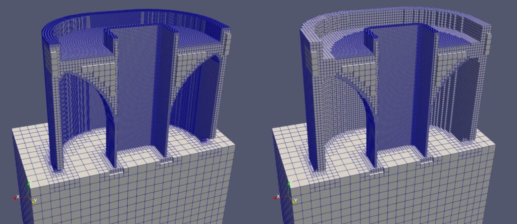
Figures 3 and 4 show meshes generated without and with feature-aware meshing, respectively. Both meshes are clipped at the central xz-plane to show interior details. The inner ring (zone 1) remains identical in both, while zones 2 and 3 show a substantial reduction in nodes and elements—summarized later in Table 1.
4. Numerical verification
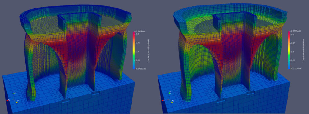
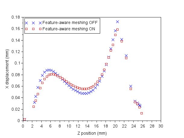
Figures 5 and 6 show displacement contours (10× warp factor) for simulations with and without feature-aware meshing, while Figure 7 compares displacements along the outer wall. The peak displacement differs by only 7.6%—0.172 mm versus 0.159 mm—demonstrating excellent accuracy retention.
Performance metrics are shown in Table 1. With feature-aware meshing, the simulation runs in one-third the time and uses less than half the RAM. Actual gains will vary based on geometry, mesh parameters, and coarsening zone definitions.
| Metric | Feature-aware meshing off | Feature-aware meshing on | Percent change |
| Nodes | 877,195 | 248,488 | -72% |
| Elements | 482,655 | 162,803 | -66% |
| Compute time | 16:39 minutes | 05:27 minutes | -67% |
| Peak RAM usage | 22.4 GB | 10.4 GB | -54% |
PRM generation
PRM generation plays a central role in Autodesk’s multi-scale additive FEA simulations. It has long been available in Netfabb Local Simulation – and is now coming to the new Fusion process simulation API.
Multi-scale simulations
Multi-scale simulations begin with a fine-scale PRM analysis of a small (5 mm × 1 mm) block of material, which captures how process parameters interact with the material. The resulting PRM file acts as a “kernel” for subsequent part-scale simulations, where it’s mapped onto each voxel of the part during layer-wise simulation steps. This method enables accurate, physics-based modeling without calibration, while supporting large voxel sizes and time steps independent of fine laser beam diameters.
Each unique combination of machine parameters and material requires one PRM generation, which can then be reused across simulation runs. Previously, PRM generation was limited to Netfabb Local Simulation.
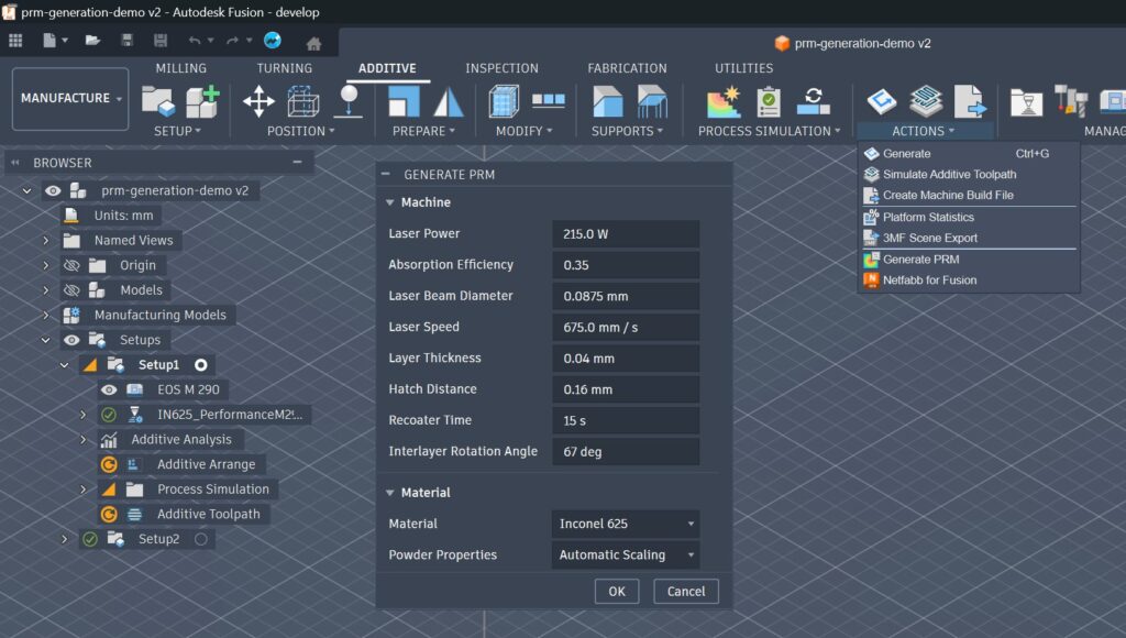
Fusion includes a library of predefined PRMs for system providers like One Click Metal, Renishaw, Aconity, and EOS – but users couldn’t easily add custom PRMs for custom process parameter and material combinations. The new PRM generation interface, shown in Figure 8, removes this limitation and will be available in the next release of 3D Printing Essentials add-in for Fusion.
With this new addition, the material selection you can simulate extends to a huge variety of special alloys and your own process parameter settings. With the accessibility through the API, automation solutions – easily scripted in Python or C++ – can ideally put process simulation in the center of design of experiments.
All at a price point that puts metal additive manufacturing into the hands of everyday machine operators – who until now had no access to any of those optimizations – and therefore needed to rely on instinct and their gut-feeling. At a high learning cost – and many failed print jobs.
Conclusion
Feature-aware meshing and PRM generation represent significant advancements in Autodesk’s additive simulation capabilities:
- Feature-aware meshing reduces simulation runtime by up to 3× and memory usage by over 50%, while maintaining displacement accuracy within 8% of a uniformly fine mesh.
- PRM generation empowers users to create and manage their own machine parameter models directly in Fusion, unlocking a broader range of machines and materials for simulation.
Together, these features enable faster, more flexible, and more accurate additive process simulations- bringing Autodesk users closer to truly predictive, scalable design for additive manufacturing.
Autodesk Fusion for Manufacturing is an incredible value proposition for any producer of metal parts. It includes industry-leading capabilities like data preparation for metal additive manufacturing, but also CAM programming for three to five axis milling and turning machines, as well as 2D and 3D Nesting capabilities for Sheet Metal production and BinderJet and Selective Laser Sintering applications.