Learn how to avoid common sketch failures in Fusion, from unconstrained sketches and open profiles to unstable parameters all while using best practices for clean, editable, parametric models.
Elevate your design and manufacturing processes with Autodesk Fusion
Sketching is the foundation of every parametric model in Fusion. When sketches are properly constrained and structured, downstream features update predictably. When they’re not, even small edits can cause failures, flipped dimensions, broken features, or timeline errors.
This guide walks through the most common sketching and parametric issues Fusion users encounter and how to fix or prevent them.
Why won’t my sketch fully constrain in Fusion and how do I fix it?
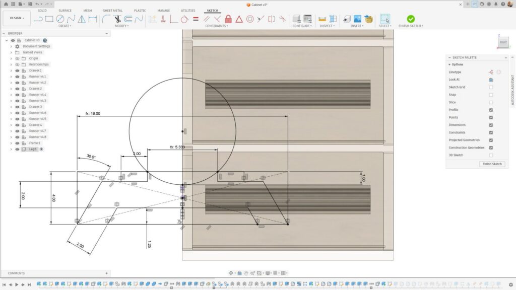
A sketch isn’t fully constrained when Fusion can still move or resize geometry, sometimes in ways you didn’t intend. This usually happens because one or more degrees of freedom are unresolved.
How to fix it:
- Turn on Show Constraints to visualize what’s applied
- Look for blue sketch geometry that can still drag (often endpoints or arcs)
- Apply Coincident, Horizontal/Vertical, Colinear, Tangent, or other constraints before adding dimensions
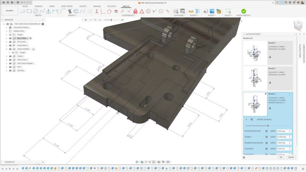
- Try AutoConstrain, this adds constraints and dimensions to your sketch to fully lock it down.
- Avoid “dimension‑only” sketches. Constraints define behavior, dimensions define size
Best practice: Fully constrain sketches before creating features. A black sketch is far more predictable than a blue one.
Why does Fusion say my proflie isn’t closed when extruding?
Fusion requires a watertight profile for solid features like Extrude. Even tiny gaps can break a profile. When a profile is closed, a light blue surface appears within the outline.
Common causes:
- Endpoints that look connected but aren’t coincident
- Overlapping or duplicated lines
- Construction geometry accidentally used as real geometry
How to debug quickly:
- Use the AutoConstrain tool to evaluate the sketch, a purple icon in the dialog shows that the tool has found something in need of repair and has fixed it
- Enable Show Profile in the Sketch palette
- Zoom in on corners and intersections
- Use Trim and Extend to clean overlaps
- Convert reference edges to Construction where appropriate
How do I use parameters in Fusion to drive model changes (without breaking features)?
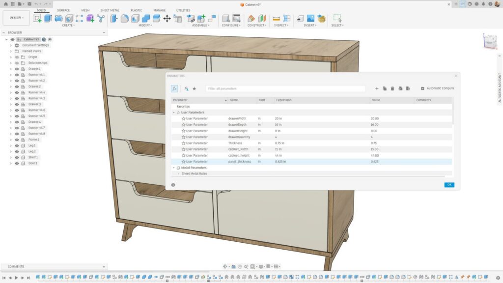
Parameters let you define dimensions once and reuse them across sketches and features, making designs easier to update. This is also a great time to implement Autodesk Assistant, describe your project and ask it to create your parameters for you.
Good parameter use looks like this:
- cabinet_width, cabinet_height, panel_thickness
- Simple formulas like shelf_spacing = cabinet_height / 4
To avoid breaking features:
- Reference parameters consistently (don’t mix hard values and variables)
- Avoid circular references
- Name parameters clearly
Parameters are especially powerful for design variants and configuration‑style workflows.
What are best practices for sketches in Fusion, including constraints, projection, and clean intent?
Sketches shouldn’t just work. They should communicate design intent.
Recommended practices:
- Constrain geometry relationships before adding dimensions
- Use Project sparingly. Projected geometry creates dependencies
- Avoid projecting filleted or changing edges
- Keep sketches simple. Split complex logic into multiple sketches
A clean sketch reduces timeline fragility and improves long‑term editability.
How do I avoid sketches in Fusion failing when editing later in the timeline?
Most sketch failures don’t happen when you create the sketch, they happen further along in the design cycle.
To prevent this:
- Avoid referencing edges likely to change downstream
- Prefer construction geometry as anchors
- Don’t overuse projected faces from features added later in the timeline
- Edit sketches in context, watching the timeline update
If a sketch fails, expand the timeline and look for downstream features that now reference invalid geometry.
How do I model scalable dimensions with parameters in Fusion?
Parametric models benefit significantly from clearly defined dimensional control.
A solid approach:
- Define top‑level parameters such as width, height, and depth
- Derive secondary dimensions using formulas rather than fixed values
- Keep all dimensions driven from a single direction using top‑down logic
This approach makes resizing and iterating on design variants fast, reliable, and repeatable—without rebuilding sketches or breaking downstream features.
When do I use construction geometry vs. real geometry in Fusion?
Construction geometry is for logic, not fabrication.
Use construction geometry to:
- Establish symmetry axes
- Define reference planes
- Control spacing and alignment
Keep real geometry limited to contours that create features. This separation makes sketches easier to read, debug, and modify.
Why do dimensions “flip” or behave unexpectedly in Fusion and how do I lock sketch intent?
Dimensions flip when Fusion doesn’t understand your intent.
Typical causes:
- Missing orientation constraints
- Symmetry not explicitly defined
- Geometry applied in an ambiguous order
How to lock intent:
- Apply Horizontal/Vertical constraints early
- Use Symmetry constraints instead of mirrored dimensions
- Fully constrain geometry shape before sizing it
The goal: tell Fusion how geometry should behave, not just how big it is.
How do I create patterns that remain editable and stable in Fusion?
Patterns are powerful, but fragile if misused.
Best practices for sketch patterns:
- Pattern simple geometry, not entire profiles
- Constrain the seed geometry fully before patterning
- Pattern distances using parameters
- Avoid patterning projected or reference‑heavy geometry
In many cases, feature patterns (in the solid environment) are more robust than sketch patterns.
How do I debug timeline errors caused by sketch edits in Fusion?
Timeline errors often surface after a sketch edit, even if the sketch itself looks valid.
Debug workflow:
- Roll the timeline back before the error
- Edit the sketch and look for removed or replaced references
- Step forward feature by feature to identify the first failure
- Reattach lost references or simplify affected sketches
Small sketch changes can ripple forward, an intentional sketch design minimizes that impact.
Strong sketching habits are the difference between models that fall apart and models that scale, adapt, and manufacture cleanly. By fully constraining sketches, using parameters intentionally, and designing with future edits in mind, Autodesk Fusion becomes far more predictable and powerful.

FAQs: Sketching & parametric design in Autodesk Fusion
Yes. Fully constrained sketches are more predictable and far less likely to break downstream features.
Yes, especially if dimensions may change later. They reduce rework and error.
Most often due to projected geometry or references to edges that no longer exist.
Many small, purpose‑driven sketches are usually more stable than one complex sketch.
Yes. Unstable sketches frequently cause failed features, broken toolpaths, and rework later.