
The latest Fusion update brings Intent Driven Design, smarter data management, and performance improvements, along with many more enhancements across design and manufacturing. Read on to see what’s new.
Table of Contents
- Minor Updates
- Highlights
- Usability
- Data Management
- Design
- Drawings
- Electronics
- Manufacturing
- API
- Insider Program
- Release Notes
Minor Updates
Our latest minor updates brings several important fixes and improvements to enhance your experience. Click to learn more.
v.2606.1.36 – February 4, 2026 (Minor Update)
Electronics
- Fixed an issue where the Processing polygons progress dialog appeared immediately when moving components inside polygon fills, even for fast operations on small boards. The dialog now appears only when polygon processing takes longer, reducing unnecessary interruptions during PCB editing.
v.2606.1.33 – February 1, 2026 (Minor Update)
Design
- When inserting a component into an empty, unsaved Part design, Fusion now provides an additional option to create a new Assembly and insert both the active Part and the inserted component. This gives you more flexibility when deciding how to organize your design.
Usability
- Fixed an issue on macOS where Fusion could quit unexpectedly on launch.
- Resolved a freeze that could occur when closing Fusion after saving a design.
- Improved reliability of crash recovery files, resolving an issue where some recovered designs could fail to open after a crash.
Highlights
v.2606.1.22 – January 21, 2026 (Major Update)
We’re starting the year with a new Fusion update that delivers meaningful improvements across the platform. From clearer design intent early in the process to expanded data and collaboration capabilities, performance gains, and workflow refinements across design, simulation, electronics, and manufacturing, this release supports teams from early design through manufacturing.
If you’d like a broader look back before diving in, our Fusion Year in Review highlights the major updates, milestones, and improvements delivered over the past year.
Usability
- Major performance enhancements
- New Graphics Interactivity Meter
Data Management
- Home tab improvements
- Bill of Materials enhancements (Collaborative Editing)
- Document management enhancements
Design
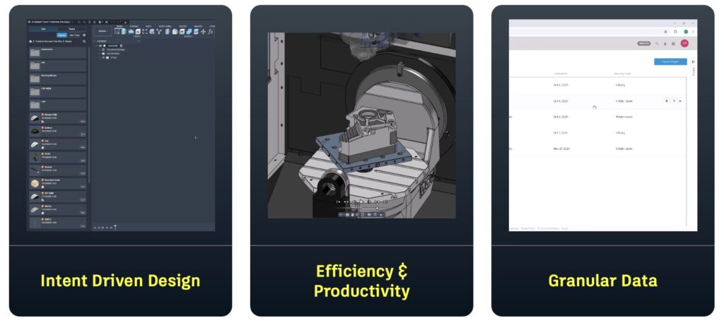
- Intent Driven Design
- Tangent constraints
- Midpoint Line
- Unified Construction Geometry
- Improved decal layering
- Configuration workflow enhancements
- Sheet metal: Hems and Flange to Object
Electronics
- New direct component importing
- New Library Attribute Editor
Manufacturing
- Turning thread automation
- Drilling fallback operations
- Multi-axis clearing
- Geodesic and Deburr enhancements
- Additive manufacturing enhancements
Usability
A Smoother, Faster Fusion
As part of our ongoing efforts to make Fusion faster and more responsive, this release includes significant foundational performance enhancements that elevate your experience. We’ve made substantial optimizations in how Fusion tracks changes, resulting in noticeable speed gains across key workflows. Here are some of the highlights:
- Isolate Operations: Up to 40–50% faster.
- Compute All Operations: Up to 30% faster.
- Mesh Conversions: Up to 35% faster.
- Opening 3MF Files: Up to 75–80% faster.
- Up to 35% faster when editing Geometric Patterns.
- Up to 3x faster when zooming into a sketch with an adaptive grid.
Note: These improvements are based on datasets provided by our customers, and performance gains may vary depending on the specific dataset.
New Graphics Interactivity Meter
View > Show Performance Overlay
Fusion now supports real-time monitoring of frame rates and video memory usage through the Graphics Interactivity Meter. Once enabled, it will appear in the bottom-left corner of the canvas, providing live performance insights as you work.
Data Management
Autodesk Fusion is the connected platform that brings teams, people, data, and processes together so you can move faster, reduce errors, and innovate with confidence.
This January release builds on that foundation with expanded data management and collaboration capabilities across Fusion.
Learn more about Collaborative Editing (CE) enhancements.
Data
To start the year strong, we enhanced the Fusion data model by launching custom properties, improving Bill of Material (BOM) workflows, delivering experience improvements, and expanding API coverage, helping you build richer intelligence directly into your Fusion models.
Custom Properties (Collaborative Editing):
Custom properties are now available for Fusion for Design and Fusion Manage subscribers. Custom Properties allow your organization to define additional component property fields unique to your business, capturing metadata such as functional, performance, compliance, or manufacturing details.
Once created, Custom Properties appear in the Property Panel and Bill of Materials and behave like standard properties, including full history tracking. They can also be referenced in Drawings (Text, Notes, Parts Lists, and Title Blocks) and are searchable in the new Home Tab Search.
To get started, Administrators can create string or numeric properties in the new Custom Properties tab in the Fusion web client Admin page.
Improved Bill of Material workflows (Collaborative Editing)
Compare to Model
When you view the latest BOM in Fusion or in the Fusion web client, a new column highlights structural differences, with color cues explaining why items diverge. Optional extended color-coding can be enabled from the Manage menu for a more detailed comparison. Blue indicates differing Shared Part Numbers and Green highlights rows that exist only in the BOM. All BOM functionality remains available when this mode is enabled.
Quantity Override
You can now adjust BOM quantities independently from your CAD model, giving you more flexibility when manufacturing or purchasing needs differ from the design. This is especially useful for adding extra fasteners for assembly, accounting for spares, or rounding up for bulk orders.
Manual overrides are highlighted in orange, and updated quantities flow through downstream workflows, including exports, helping teams stay aligned.
Improved Save & Replace Experiences
Save As and Replace now supports including related drawings. In the Save As dialog, use the Include Drawings option to copy associated drawings so they correctly reference the new design, reducing manual cleanup and rework.
Search and Discoverability
This release includes several enhancements that improve how you search for and discover data within Fusion, including property search in the Home Tab, a new Details Page, icon updates in the Data Panel, and other experience improvements.
Note: We’ll be releasing this new search functionality slowly over the next few weeks. So, if you don’t see it today, you should see this functionality in your Collaborative Editing hubs very shortly.
New Home Tab Search enables property search (Collaborative Editing)
We launched powerful new search capabilities in Home Tab that supports searching for more than two dozen properties, like Vendor and Manufacturer Part Number, along with any custom properties your organization defined.
You can still search file names and part numbers, and results now include richer property data to help you find relevant information more quickly and keep workflows moving.
New Home Tab Details Page (Collaborative Editing)
Designs can get complex, especially when parts are shared across designs and drawings. To help you better understand these relationships, we added a details page for your designs within the Home Tab showing properties, uses, used-in, and drawing details.
Assembly/Part icons added to the Data Panel
The Data Panel now includes part and assembly icons to help identify design intent at a glance. This update supports the default shift toward using external components within assemblies. For parts with hybrid intent or legacy Fusion designs, no icon is shown.
Collaboration
Consolidate Historical Records
We upgraded the History Panel to make reviewing updates clearer and easier to follow. Consecutive record types are now consolidated, resulting in a cleaner, less cluttered history view.
Versions and Revisions will remain separate, ensuring these key milestones are easy to spot when you need them.
The result is a more streamlined, less overwhelming way to track changes so you can stay focused and move through your work with confidence.
Desktop Connector Enhancements
Desktop Connector now includes improved error handling and greater control during uploads, making it easier to manage files and catch issues earlier. It provides a virtual Fusion drive on your Windows desktop, allowing you to store files directly in Fusion projects and access them from anywhere.
To support troubleshooting, you can filter for files with issues, view parent files for missing references, and re-resolve files once problems are fixed. The Upload dialog now flags invalid files immediately, helping you identify and address issues earlier in the process.
Design
Intent Driven Design is here
Ever had to make components from bodies because you forgot to start with a new component? Or ended up with the wrong sketch or construction geometry in the wrong place because you forgot to activate the right component? Maybe you’ve even had to ping a colleague to “save and get out” of a design because you wanted to work on another part of the assembly.
If any of that sounds familiar, you’re not alone.
Intent Driven Design has been available in preview for some time, and it is now the default behavior in Fusion. Intent Driven Design gives you a choice up front: what do you want to design?
By choosing Parts and Assemblies, Fusion guides you down a structured path, with a focus on maintaining discipline across two streamlined environments. Hybrid is ideal for smaller, isolated assemblies or early ideation projects, while Parts and Assemblies provide clearer separation and control for more structured workflows.
The key point is that you decide. And most importantly, if you later realize you made the wrong choice, switching paths is a simple change in Document Settings.
Learn more about Intent Driven Design, including detailed explanations and tutorial content to help you get up to speed quickly.
New Tangent Constraint
This release adds Tangent Constraints to Fusion, expanding our growing set of assembly constraints. Tangent Constraints let you easily define tangency between faces or edges, making it easier than ever to model realistic mechanical assemblies. With the new All Faces selection option, you can choose whether the tangency propagates across adjacent faces, perfect for cam-style behavior, or remains fixed to a single surface.
Unlike the previous Tangent Relationship, this new constraint type also supports face-to-edge selections, giving you more flexibility in how components interact. You’ll still find Tangent Relationships in the toolbar, but selecting them will guide you into the new Constraints dialog with the Tangent type pre-selected as we complete the transition.
Unified Construction Geometry Workflow for Faster, Easier Design
Construction geometry often sits behind the scenes, guiding the design without drawing attention to itself, and this update is designed to make working with it feel far more fluid. The new Unified Construction Geometry Workflow brings planes, axes, and points into a single, flexible dialog, allowing you to move between all nineteen construction methods without stopping or restarting the command.
As you work, you can switch from creating a plane to defining an axis or a point simply by changing the Type selector. Every method available for that type will appear in the same streamlined interface.
When you explore different approaches, the workflow carries over any matching inputs automatically, so if you begin by selecting a face or an edge, that selection follows you when you try another method. This makes it easy to iterate, compare options, and refine your intent without repeating steps. The update also merges the previous Tangent Plane tools into one clearer command, so both capabilities now live in the same place.
To use the unified workflow, open any construction command from the Construction panel and begin defining your geometry; from there, you can shift types or methods at any time, test alternate solutions, and build up complex reference geometry in a single uninterrupted flow.
Learn more about construction geometry.
Reverse surface normals inside the Patch command
We added a new checkbox in the Patch tool that lets you reverse the normal of created surfaces, helping declutter your timeline. We’ve also added a Flip button for quickly toggling the surface normal.
Learn how to Patch open areas on a surface body
Enhanced Decal layering order control
Decals now respect the order shown in the browser, with the decal at the top of the list appearing on top visually. This update resolves a long-standing issue where multiple decals on the same surface did not follow browser order, which often led to unpredictable layering. You now have reliable control over which decal appears above others, improving workflows that rely on stacked or overlapping decals.
To use this enhancement, simply add multiple decals to your model and adjust their order in the browser. Drag decals up or down in the list, and Fusion will display them accordingly, with the topmost entry appearing on top in the scene.
Streamlined Configuration Table Edits
You can now edit all cells in a configured Suppression or Visibility column at once in the Configuration Table. This new feature significantly reduces the time and effort required for repetitive table edits in complex configured designs.
Simply right-click any Suppression column to open the context menu and choose from Suppress All, Unsuppress All, or Invert to make bulk changes. Similarly, for Visibility, right-click the desired column and select Show All, Hide All, or Invert.
Learn how to configure feature suppression.
Learn how to configure object visibility.
Enhanced Rectangular Geometry in Sketch
Now, within Rectangular geometry in Sketch, you can select a construction geometry axis to set the direction. This enhancement enables more precise and controlled sketching, improving your overall workflow efficiency.
Midpoint line in Fusion Sketch
A new Midpoint Line command provides an additional way to create lines by selecting the midpoint first and defining the second point.
Feature Pattern Compute Type now Defaults to Identical
When working with Mirror or Pattern commands (Rectangular, Circular, or Path), you will notice something new. The default Compute Type has been updated to Identical, rather than Adjust, giving you a faster and smoother experience right from the start.
This choice is remembered for the rest of your Fusion session. If you switch to Optimized or Adjust, Fusion will apply that preference to every new pattern you create until you close the app. It is a small change that keeps your workflow feeling natural and uninterrupted.
New Mesh repair rebuild type
A new rebuild option has been added to the Repair command. Adaptive rebuild type repairs the mesh using a varying mesh density, using a higher density mesh at key feature locations.
Automated Modeling in Edit in Place mode
Automated Modeling can now be used directly in Edit in Place mode, allowing you to explore design alternatives while staying in the full assembly context. Selected faces and bodies are highlighted according to Edit in Place display settings for clear, consistent visual feedback. When you generate outcomes, Fusion creates the required assembly context automatically so reference objects are captured in the timeline and future edits remain associative. This supports more top-down workflows, reduces rework, and helps preserve design intent as assemblies evolve.
To use it, activate Edit in Place on the component, open Automated Modeling, select the faces you want to connect and the bodies you want to avoid, review the outcomes in context, and commit to a result.
Sheet Metal
New Sheet Metal Hem
A new Hem feature is now available, giving you a complete toolset for creating Open, Flat, Rolled, Rope, Teardrop, and Double Hems directly within your Sheet Metal workflow. Hems play an important role in both function and manufacturability, and this update makes them easier than ever to apply. You can use hems to remove sharp edges for safer handling, add rigidity to thin material, improve the appearance of your parts, hide burrs or rough edges, protect cables, support interlocking or folded joints during assembly, reduce corrosion on exposed edges, and ensure better alignment when fitting parts together.
With this release, you can access the Hem command from the Create menu in the Sheet Metal tab, select the hem type you need, and apply it to any qualifying edge with full control over size and behavior. The feature also works with the API, so you can automate hem creation through scripts or custom add ins. If you use the Design Extension, you will also see support for Hem presets, allowing you to save and reuse your preferred settings.
Learn how to create a Hem.
New Flange to Object
Flange to Object is here giving you a new way to define flange length by referencing existing geometry. Much like Extrude to Object, this option lets you pick a face, edge, or body as the end point for your flange, allowing the feature to adapt automatically when that reference moves. This gives you a more flexible and intent driven workflow, especially when your design relies on relationships between sheet metal features or surrounding components.
When you use Flange to Object as the Extent Type, the flange length updates for you, keeping your model consistent without extra edits. For now, this option supports creating one flange per operation, but it already provides a more intelligent and responsive way to control flange behavior as your design evolves.
Learn how to use Flange to Object.
Drawings
Enhanced Drawing Automation Experience
We improved the Drawing Automation workflow to make it faster and easier for you to access and apply automation settings when creating drawings. Automation Preferences are available directly in the Create New Drawing dialog, allowing you to review and update your settings at the start of the process. These preferences are also displayed as a dedicated tab within drawing templates rather than being located under Document Settings, making them more visible and easier to access.
With this enhancement, you can adjust Automation Preferences before generating a drawing, choose whether to create automated drawings with or without templates, and save your customized settings as a new template for future use.
To use the updated experience, open the Create New Drawing dialog, review the Automation Preferences, make any required changes and generate the drawing. You can also save these settings as a new template if you plan to reuse them.
Learn how to manage automation preferences.
Display Configuration Tables in Drawing Sheets
You can now display Configuration Table data from Design directly on a drawing sheet, making it easier to document configurations and create Tabulated Drawings without manually retyping configuration data.
Configured aspects from the Design workspace can be shown directly in drawings. You can replace dimension values on a sheet with configured aspect names to document multiple configurations of a design in a single tabulated drawing. Columns from the configuration table in Design can be shown or hidden to focus the table on only the information you need for your drawing.
Learn how to create a tabulated drawing for a configured design.
Show Drawing Counts in Save Workflows
In this update, the Save As, Save As and Replace, and Save Copy As workflows now show you the exact number of associated drawings that will be copied as part of the operation. Previously, this information was hidden, leaving you to infer how much downstream data would be generated.
By making drawing counts visible up front, this enhancement gives you greater clarity and control, helping you anticipate the scope of your changes and manage your data more confidently. It’s a small but meaningful improvement that brings more transparency to the way Fusion handles design documentation.
Hub Level Custom Properties Support in Drawings
You can now add Hub level custom properties to capture metadata that describing your components’ functional, performance, compliance, manufacturing, etc characteristics. These properties will be available in Fusion Drawings to place in the canvas in the form or Text, Note or in Parts list and title block. As you place these properties, the values will be evaluated and displayed on canvas. Any further change in the value of placed properties will be auto-reflected in the Drawings.
Electronics
Redesigned Attribute Editor
The Attribute Editor has been redesigned for a more efficient and flexible library authoring experience. You can now:
- Create attributes for variants, components, and libraries that share values across attribute sets
- Copy attribute lists between attribute sets
- Modify or rename attributes without using ULPs or manually updating each component
Learn more about component Attributes.
Direct Component Importing
You can now import components from a local library file directly into an existing library in the Library Authoring workspace. This makes it easier to bring in components without adding extra clutter to your project folders.
Exclude Design Data from Scopes in Custom Design Rules
You can now apply “NOT” conditions to scopes directly in the Design Rules Editor to exclude certain data when checking a given rule.
Additional Electronics Enhancements
In addition to these updates, January includes several new enhancements for Electronics.
Learn More
Keyboard Shortcut for Quick 2D PCB Layer Navigation
A new keyboard shortcut (CTRL/⌘ + ↑/↓) lets you quickly move between display layers. You can also use LAYER INCREMENT or DECREMENT in the Command Line Interface. This streamlines navigation and boosts design efficiency by reducing reliance on menus or mouse clicks.
Inline Document Attributes Support
Document attributes can now be embedded directly within text strings, not just as standalone references. This update enables more dynamic content creation and improves workflow flexibility.
Board Orientation Visibility
We’ve added a visible Flip Board status indicator to help you stay oriented in 2D PCB. The toggle now highlights when active, and the Bottom layer becomes the default view when flipped.
Datasheet Attribute
Newly created components now include a default set of base attributes, including a Datasheet attribute. You can now access the datasheet directly from the Place Panel for any component that has this datasheet attribute.
Manufacturing
Milling
Multi-Axis Clearing Toolpath Strategy (Manufacturing Extension)
A new Multi-Axis Clearing toolpath strategy is now available. This strategy can clear out areas such as pockets with curved floor surfaces. The strategy creates a toolpath by offsetting from the floor surface, a ceiling surface, or by blending between the two. The user can choose between Pocket or Adaptive styles. The strategy can also support 3- and 4-axis workflows. It can additionally be used to machine undercuts.
Learn more about Multi-Axis Clearing.
New Options for Geodesic
Two new options have been added to the Geodesic toolpath strategy when using the Blend type. The first of these allows intermediate curves to be included in the drive curve selection, alongside the start and end curves. The drive curves can be specified in any order and the strategy will determine the start, end and intermediate curves. The second is a new parameter on the Passes tab called ‘Smooth Stepovers’. When the strategy is blending between curves this will automatically insert intermediate curves. Both of these options can be used to reduce sharp corners in the toolpath and produce a smoother result.
Learn more about the Geodesic milling strategy.
New Options for Deburr (Manufacture Extension)
Two new options have been added to the Deburr strategy to help control the edges that are selected to deburr. You can now choose to exclude vertical edges (3-axis only) or exclude circular holes within a diameter range.
Learn how to generate a Deburr toolpath.
Improvements to Import CAM Data for Linked Designs
In November, we enhanced the Import CAM Data for Linked Designs workflow to allow redefining the Workpiece Coordinate System (WCS), making it easier to reuse pre-programmed CAM parts in different orientations. Since then, we’ve addressed a few additional issues, including support for adding fixture components to a setup and fixing a problem that prevented changing the Part Position when using a simulation machine.
Learn more about how to insert a design with setups into the current document.
Drilling
New Fallback Operations for Drilling
It is now possible to add ‘fallback’ operations to hole templates using the Hole Template Editor. These are drilling operations which only run if the previous operation is unable to machine all the holes due to collision avoidance.
A fallback operation may, for example, use a longer tool so it is able to reach holes which the original drilling operation could not. Multiple fallback operations can be chained together so you can try different tool lengths to machine all the holes and only use a longer tool where required. Fallback operations can also be created outside of hole templates using the ‘Remaining holes from operation’ Selection Mode on the Drill strategy.
Learn how to create a hole template.
Turning
New Automatic Definition Mode for Turning Thread
Added an “automatic” thread definition method to turning thread strategies where users will now be able to re-use thread parameters specified in the design space to program a threading toolpath without re-entering those parameters in the manufacturing space.
Learn how to generate a Turning Thread toolpath.
Additive Manufacturing
New Delete Supports for Additive Setups
A new Delete Supports operation is now available for Additive setups in the Manufacture workspace. This tool offers precise control, enabling you to target and remove specific sections of the support structure. With a range of selection and removal options, you can fine-tune exactly which areas of support to eliminate, ensuring optimal printability and easier post-processing.
Learn how to Delete Supports.
Duplicate supports as well as components
Additionally, you are now able to specify whether you want the support structure of a model to also be duplicated within the Duplicate command. If you choose to duplicate your supports with this new tool, you also have the option to either create a New Support operation(s) or keep the existing Support Operation(s) in the browser. If you chose to create a New Support operation, all the support operations applied to the source component will be duplicated for each new component.
Additive Arrange: New Solver Tab with Interlocking Prevention
Interlocking components cannot be separated after 3D printing, so it’s essential to generate arrangements that avoid this issue. To support this, we’ve introduced a new Solver tab in the Additive Arrange dialog for both 2D and 3D True Shapearrangement types. This tab allows you to choose whether interlocking checks should be performed during arrangement.
To help you achieve high packing density without risking interlocking, the Solver tab provides two configuration methods:
- Translational – Simulates a “de-nesting” process by verifying that each component can slide out of the build area along a single axis without colliding with neighboring parts.
- Bounding Box – Performs a quick, simplified overlap check using prismatic bounding boxes to ensure outer part boundaries do not intersect.
As part of this update, the Bounding Box method is now integrated directly into the Solver tab for both 2D and 3D True Shape arrangements. Because of this consolidation, the separate 3D Arrange (Bounding Box) option has been removed from the Arrangement Type list.
The updated list of arrangement types now includes:
- 2D Arrange (True Shape)
- 3D Arrange (Monte Carlo)
- 3D Arrange (True Shape)
Export your slice data with 3MF
We have added an option to the 3MF Scene Export command that uses the 3MF Slice Extension to export slice data. This enhancement allows you to represent 3D models as stacks of 2D slices, enabling more efficient data sharing. The layer thickness for each slice is determined by the print settings assigned to each setup.
New Additive Analysis folder
As we continue to expand functionality, keeping data organized and accessible remains essential. To support this, we’ve added an Additive Analysis folder to the setup, bringing platform and print statistics together in one centralized place.
Post Processor and Machine Simulation
Looking for the latest post processors and machines updates? This January we released a ton of new updates and improvements to many of the open-source Post Processors and Machines we offer for free. Within this release you will find improvements to post processors including Generic Post Processors, Milling Post Processors, and Turning Post Processors. We also added new machines to our Machine Library, updated our Workholding library, and improved functionality around the Autodesk CAM Post Processor engine.
Learn what’s new for Post Processors and Machine Simulation this January.
API
We have introduced multiple new APIs to give you greater control and flexibility.
Learn More
API Changes to Support Design Intent
This release introduces a new design-intent experience with three design types: hybrid, part, and assembly. Hybrid is the design type that Fusion has always supported. The part and assembly design types are new. If you use the Hybrid design type, there is no change. However, for part or assembly designs, there are significant changes to the user interface and how Fusion behaves. This also affects add-in commands, and most will need to be updated to handle it correctly. For more information, see the new Programming for Design Intent topic in the API User Manual.
If you need access to the functionality provided by an add-in that hasn’t been updated, you can always revert back to using a hybrid design.
New API functionality has been added to support this. These are the Design.designIntent, Design.isModelingInAssemblyEnabled, Occurrences.addNewExternalComponent, and the Spur Gear sample program have been updated to fully support the new design types. Some of the other samples have been modified to check that you’re in the required design type and will exit with a warning if you’re not.
Updated User Interface Themes
With the introduction of the dark user interface theme in Fusion, only two themes are now supported: light gray and dark blue. The User Manual topic on the user interface has been updated to discuss the icons used for different themes. If you have created custom commands, you will likely need to add icons for your commands and for any icons shown in dialogs, so they will display correctly when the user selects the dark blue theme.
API Support for Derive
The API now supports deriving components. This includes the ability to create, query, and edit a Derive feature and to query the entities that can be derived to determine if they were derived, and if they were, which derive feature created them.
API Support for Sketch Auto Constrain
The API now supports the auto constraint functionality in sketch. This functionality is a preview, so please use it and provide feedback on what you liked or didn’t like.
Python Update
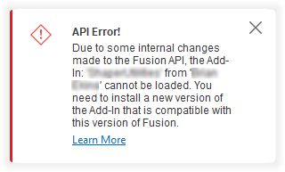
This Fusion release updates the Python version from 3.12 to 3.14. Besides the API, Fusion uses Python for a few other things, and this Python update includes security fixes. Most people won’t notice any change. Those affected are the developers and users of any Python apps delivered as .pyc files. Previous versions of these add-ins will be broken because .pyc files are tied to the minor version of Python that was used to create them. Add-ins compiled with the current version (3.12) will not be compatible with the new release (3.14) and will fail to load. This change does not affect any add-ins where the .py source code is available.
If you deliver apps as pyc files, you need to test your add-in and rebuild it to get new pyc files that you can make available to your users.
If you’re a user and see the message shown below when you start Fusion, you have an impacted add-in and need a new version. Check the Autodesk App Store or the developer’s website to download a new compatible version, install it, and continue using it as before. If you can’t find an updated version of the app, contact the app developer directly.
Insider Program
Do you want to engage more with the Autodesk community? Check out the Fusion Insider program to use exclusive previews, and test out the latest build before it’s released to the public.
As a member, you’ll gain inside knowledge of updates and a first look at new features. You’ll also be able to join exclusive events and try pre-release functionality. Plus, you can give feedback directly to the product teams.
Release Notes
But wait, that’s not all! To see more fixes, minor enhancements, and keep up with the latest check out our Release Notes for more information on changes to Fusion and Fusion web client.