Learn everything about the ohm (Ω), the SI unit of electrical resistance—from Georg Simon Ohm’s discovery and Ohm’s Law to practical applications, AC impedance, and modern quantum standards in electrical engineering.
Whenever you plug in a device or flip a switch, you witness the fundamental principles that Georg Simon Ohm discovered nearly two centuries ago. The ohm, symbolized by Ω, is the cornerstone unit for measuring electrical resistance in our modern world. From household circuits to sophisticated quantum measurements, understanding the ohm is essential for anyone working with electricity.
This guide covers everything you need to know about the ohm, from its historical origins to modern applications in electrical engineering.
What is an Ohm?
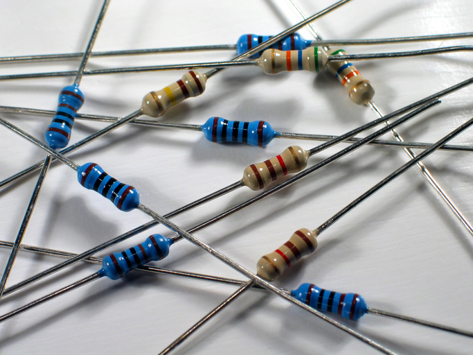
The ohm is the SI unit for measuring electrical resistance, quantifying how much a material opposes the flow of electric current. It is defined as the resistance between two points of a conductor when one volt applied across these points produces a current of one ampere.
Mathematically:
1 Ω = 1 V/A
Where:
- Ω (omega) represents ohms
- V represents volts
- A represents amperes
The ohm is central to the SI system of electrical units, connecting directly to volts (electric potential) and amperes (electric current), making it a derived unit but an essential one in electrical engineering.
Common multiples of the Ohm
- Kiloohms (kΩ): 1,000 ohms
- Megaohms (MΩ): 1,000,000 ohms
- Microohms (μΩ): 0.000001 ohms
These multiples facilitate working with various resistance values found in practical electrical systems, from tiny resistances in superconductors to large resistances in insulators.
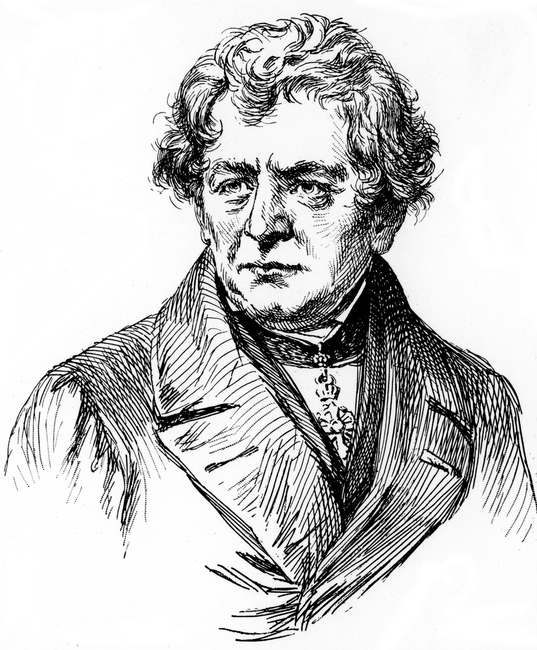
Georg Simon Ohm and historical background
Georg Simon Ohm (1787-1854) was a German physicist and mathematician who laid the foundation for our understanding of electrical circuits. Initially a mathematics teacher, Ohm turned to electricity in the 1820s, conducting experiments with galvanic cells and various conductors to measure the relationship between voltage, current, and resistance.
He published his findings in 1827 in “The Galvanic Circuit Investigated Mathematically.” Initially met with skepticism, his work was later recognized, and in 1861, the term “ohm” was proposed by the British Association for the Advancement of Science to standardize electrical units, officially adopted in 1881.
Ohm’s law and fundamental relationships
Ohm’s Law states that the current through a conductor between two points is directly proportional to the voltage across the two points and inversely proportional to the resistance.
[ V = I \times R ]
Where:
- ( V ) = voltage (volts)
- ( I ) = current (amperes)
- ( R ) = resistance (ohms)
Rearranged to solve for any variable:
[ I = V/R \quad \text{or} \quad R = V/I ]
Ohm’s Law applies to linear resistors and ohmic materials under constant temperature conditions. It helps calculate power consumption, design circuits, troubleshoot systems, and ensure proper component ratings.
Limitations
Ohm’s Law doesn’t apply to non-linear components (e.g., diodes, transistors), materials with temperature-dependent resistance changes, AC circuits without considering impedance, or superconductors with zero resistance.
Calculating resistance in DC circuits
Applying Ohm’s Law in DC circuits involves straightforward steps:
- Measure or identify the voltage across the component.
- Measure or calculate the current through the component.
- Apply Ohm’s Law: ( R = V/I ).
- Check units to ensure the result is in ohms.
Example: A 9V battery with a current of 0.5A results in a resistance of 18Ω ( ( R = 9V / 0.5A = 18Ω )).
Resistance sources include resistors, conductors, internal resistance of power sources, and contact resistance. Measurements are done using digital multimeters or other techniques while considering the circuit’s conditions.
Impedance and AC circuit applications
In AC circuits, impedance (Z), also measured in ohms, includes resistance (R) and reactance (X):
[ Z = \sqrt{R^2 + X^2} ]
With:
- Inductive reactance (( X_L )): ( X_L = 2\pi fL )
- Capacitive reactance (( X_C )): ( X_C = 1 / (2\pi fC) )
Reactance depends on frequency and reactive components like inductors and capacitors. RMS values for voltage and current are used to accurately represent power dissipation.
Practical applications include audio systems, power transmission, filter circuits, and motor control. Understanding impedance is essential for AC circuit analysis, filter design, and power system engineering.
Relationship to other electrical units
The ohm is coherently connected to other SI units:
- Volts: Drives current through resistance
- Amperes: Current flow determined by voltage and resistance
- Watts: Power dissipation
Power dissipation formulas:
[ P = V^2/R \quad P = I^2R \quad P = VI ]
Conductance (G), the reciprocal of resistance, is measured in siemens (S): ( G = 1/R ).
Modern standards and measurement
The definition of the ohm has evolved, with the quantum Hall effect providing unparalleled precision since 1990. Temperature, humidity, electromagnetic interference, and mechanical stress can affect resistance measurements. National institutes maintain quantum Hall devices as primary standards, ensuring accuracy across applications.
Ohm practical applications and examples
Understanding ohms in practical applications bridges theoretical knowledge and real-world use. Examples include:
- Audio systems: Matching speaker impedance with amplifiers ensures efficiency and quality.
- Component specifications: Resistors, fuses, heating elements, and sensors rely on precise resistance values.
- Circuit design: Select resistance for current limiting, voltage division, and impedance matching.
- Troubleshooting: Use resistance measurements to diagnose open circuits, short circuits, and component failures.
- Safety: Resistance plays a role in ground fault protection, arc fault detection, overcurrent protection, and insulation testing.
Understanding ohms is vital across basic maintenance, advanced electrical engineering, and scientific measurement standards.
Understanding the fundamentals of electrical resistance is the first step toward designing successful electronic circuits. With Autodesk Fusion for Electronics, you can seamlessly model, simulate, and validate PCB layouts and electronic assemblies—ensuring components meet resistance specifications and system performance requirements.