If you’re getting started with assemblies in Autodesk Fusion, this is a great place to start. This guide highlights important tools to master, best practices, and things to be aware of as you get up to speed with assemblies in Fusion.
Elevate your design and manufacturing processes with Autodesk Fusion
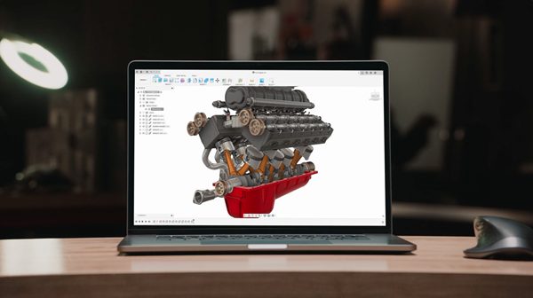
When designing complex products in Autodesk Fusion, understanding fusion assembly fundamentals is crucial. Assemblies in Fusion let users organize, simulate, and manage multiple components in a single, cohesive design environment. This guide explores the essential tools and techniques for efficient and accurate assembly in Fusion, helping both beginners and advanced users unlock the full potential of assemblies in Fusion.
Understanding assemblies in Fusion
Assemblies in Fusion are groups of individual parts or components, brought together in one design to analyze how they interact. The hierarchical component browser in Fusion makes it easy to organize assemblies in Fusion, navigate between subassemblies, and edit the structure of your fusion assembly efficiently. Techniques such as using assembly context and exploded views help users manage different configurations and visualize how assemblies in Fusion fit together or come apart.
When working with assemblies in Fusion, it’s important to understand the difference between top-down and bottom-up approaches. In a top-down workflow, you start with a master layout or skeleton at the top level and progressively add detail, establishing relationships and constraints between components for flexible, parametric modeling. In contrast, a bottom-up approach involves assembling pre-made parts or components without a hierarchical structure, which is ideal for standard or less variable parts. Choosing between top-down and bottom-up depends on the complexity and variability of your design.
To create an assembly in Fusion, start by organizing your components and bodies for clarity and reusability. Following best practices for naming, grouping, and structuring your assembly will help maintain order as your design grows.
Essential Fusion assembly tools
Here are six essential tools every user should know to understand the concept of assemblies in Fusion 360:
- Component browser: The component browser is the backbone of assembl in Fusion. It allows you to manage and organize components within an assembly. It also provides a hierarchical view of the assembly structure, making it easy to navigate, edit, and control the individual components. The browser also helps manage both components and bodies—bodies can serve as foundational elements for organic shapes and flexible modeling, and can be copied, pasted, or iterated before converting to components. The top level component acts as the anchor of your assembly structure, providing a clear hierarchy for subassemblies and parts.
- Assembly context: Assembly context allows you to create multiple variations or configurations of an assembly within a single design. It enables you to manage different states of your assembly, such as exploded views for assemblies, subassemblies, or alternative component positions, providing flexibility and control over design iterations.
- View representations: View representations enable you to create and manage different views of your assembly. You can define specific component visibility, position, and display settings for each view, making it easier to communicate and document different aspects of your design. You can also manage internal and external components within the current design, and use files to organize assemblies and maintain a clear workflow.
- Exploded views: The exploded views tool lets you visually communicate the Fusion assembly process or disassembly sequence by creating exploded views. You can precisely control the position, orientation, and spacing of components, showcasing how they fit together or come apart.
- Section analysis: Fusion offers section analysis tools that allow you to slice through your assembly and examine the internal details. You can create cross-sectional views to gain insights into the component relationships, clearances, and interference, facilitating design validation and verification.
- Design timeline: The design timeline enables you to visualize and control the sequence of events within an assembly. You can use it to track changes, dependencies, and assembly animations, providing a clear overview of the assembly’s evolution.
Creating and manageming Fusion assemblies
Insert component The insert component tool allows you to bring in external models or create new components directly within a Fusion assembly. You can insert an external component and manage its visibility or apply overrides as needed. For better organization, you can also create internal components within the assembly file and control their visibility directly in the design environment. The tool uses a radio button interface in Fusion, letting you select between creating internal or external components during the assembly process. This tool enables you to assemble complex designs by combining various pre-existing or newly created components.
Component properties: With component properties, you can define and modify the properties of individual components, such as material, appearance, or mass. You can activate a specific component or feature to focus on editing its parameters without opening new windows. When positioning or constraining components, carefully choosing reference points like edges, faces, or midpoints improves assembly accuracy and efficiency. This feature facilitates accurate representation and analysis of the assembled components.
Techniques
- Utilize assembly patterns to create multiple instances of components that repeat in a specific pattern or sequence. This can significantly speed up the assembly process and facilitate design modifications.
- Explore the use of derived components to create variations of existing components within the assembly without modifying the original part.
Factors to consider
- When managing components, be mindful of any design changes or updates that may affect the assembly. Fusion provides the ability to track and manage these changes using the timeline and rollback feature.
- Always review and validate the impact of any modifications on the Fusion assembly structure and component relationships to ensure the design integrity is maintained.
Applying constraints and joints in Fusion assembly
Applying constraints and joints to assemble components is a fundamental aspect of Fusion 360. Assemblies are open and unconstrained until joints or constraints are applied, allowing for flexible positioning of components in the early stages of design. You can precisely define the relationships and behavior between components with a wide range of constraint types available.
Whether it’’s constraining parts’’ position, orientation, or motion, Fusion 360 offers intuitive tools to ensure accurate assembly. Joints allow you to simulate realistic motion and interactions between components, enabling you to validate and refine your designs. You can create robust and functional assemblies in Fusion 360 by leveraging these powerful constraint and joint features. When applying constraints and joints, it is important to find the correct geometry or reference points for joint placement to ensure proper alignment. You can create robust and functional assemblies in Fusion 360 by leveraging these powerful constraint and joint features.
The process of applying constraints and joints involves several steps: first, select the components, then choose the appropriate constraint or joint type, and finally adjust parameters as needed. Following these steps in a step-by-step manner ensures systematic and accurate assembly. When applying constraints, you may choose to leave certain degrees of freedom unconstrained if flexibility is needed for your design.
Here are five advanced tools every user should know about when applying constraints and joints to assemble components in Fusion:
- Joint types: Fusion offers a variety of joint types to establish relationships between components within an assembly. Explore advanced joint types such as cylindrical, spherical, planar, and universal joints. These joints allow for precise control over the movement and interaction of components, enabling realistic assembly simulations. Understanding the difference between similar constraints, such as coincident vs. tangent, is essential for accurate assembly.
- Motion links: Fusion provides the ability to create motion links between components. Motion links allow you to define specific motion or movement between components, such as rotational or translational motion. By utilizing motion links, you can accurately simulate the functionality of your assembly and analyze its behavior.
- Design accelerators: Fusion includes design accelerators that streamline the process of adding constraints to your assembly. These accelerators provide quick and automated ways to apply common constraints, such as coincident, tangent, or flush constraints. They help save time and simplify the constraint application process. You can highlight key relationships or constraints for clarity during assembly, making it easier to troubleshoot or communicate design intent.
- Flexible joints: Fusion offers flexible joint options that allow for controlled movement and deformation of components within an assembly. You can apply flexible joints to simulate the bending, twisting, or stretching of parts, providing a more realistic representation of how the assembly behaves in real-world conditions.
- Contact sets: Fusion provides contact sets that enable you to define and simulate contact interactions between components. Contact sets allow for realistic physical interactions, such as collisions or sliding, between components within an assembly. This is particularly useful when analyzing the behavior of assemblies with moving or interacting parts.
Understanding and utilizing these tools will enhance the accuracy and functionality of your assembled designs.
Fusion assembly workflow best practices
- Use distributed design to create components in separate files, then combine them in a top-level fusion assembly. This supports updates and collaboration.
- Try multi-body design for top-down modeling, generating multiple bodies within a single Fusion file and converting them into components for your fusion assembly.
- Track changes and dependencies using the design timeline, offering a visual overview of how assemblies in Fusion evolve.
Simulating and validating assemblies in Fusion
Use section analysis to slice through your fusion assembly for internal inspection, and animated features to simulate realistic movement. These powerful tools help validate clearances, avoid interference, and ensure functional assemblies in Fusion.
Here are five tools every user should know about for animating and simulating assemblies in Fusion:
- Joint motion: Fusion allows you to define and control the motion of joints within an assembly. By setting joint parameters such as rotation angles, limits, or ranges, you can animate the movement of components. This tool enables you to visualize how your Fusion assembly functions and validate its kinematic behavior.
- Exploded views: Fusion offers the ability to create exploded views of assemblies. With this tool, you can disassemble components and show their individual parts in a clear and organized manner. Exploded views help communicate Fusion assembly sequences and provide a better understanding of how components fit together.
- Motion studies: Fusion provides capabilities, allowing you to simulate and analyze the dynamic behavior of assemblies. You can define motion paths, simulate forces and loads, and evaluate the performance of moving parts. Motion studies enable you to assess the functionality, clearance, and potential interferences within your assembly.
- Physical simulation: Fusion includes tools for performing physical simulations on assemblies. You can apply realistic material properties, define contacts and constraints, and simulate the behavior of the assembly under various load conditions. This tool helps validate the structural integrity and performance of your design.
- Stress analysis: Fusion offers stress analysis tools that allow you to evaluate the structural integrity of assemblies. By applying loads and constraints to your design, you can analyze stress distribution, deformation, and safety factors. This tool aids in identifying potential weak points and optimizing the design for strength and reliability.
By utilizing these tools, you can animate and simulate Fusion assemblies, gaining valuable insights into their functionality and behavior.
Techniques
Joint selection and type: When applying constraints and joints, it’s crucial to select the appropriate joint type based on the desired behavior. Fusion offers various joint types such as revolute, slider, cylindrical, and more. Understanding the purpose and characteristics of each joint type allows you to choose the most suitable one for the assembly. Additionally, ensure accurate joint selection by carefully identifying the desired connection points between components.
Constraint limitations: It’s important to be aware of constraint limitations and their impact on the assembly. Fusion has specific constraints that enforce the desired relationships between components, such as coincident, concentric, or parallel constraints. However, applying too many constraints or conflicting constraints can result in unintended consequences. Be mindful of constraint limitations and avoid over-constraining the assembly, which can restrict the desired motion or cause assembly instability.
By carefully selecting the appropriate joint type and understanding constraint limitations, you can effectively apply constraints and joints to assemble components in Fusion. These techniques help ensure the desired motion and behavior of the assembly while avoiding over-constraint issues that may compromise functionality.
Comprehensive Getting Started Guide
- Welcome to Autodesk Fusion 360: Guide to Getting Started
- Autodesk Fusion 360 Basics: Getting Started with Sketching
- Autodesk Fusion 360 Basics: 3D Modeling Made Easy
- Autodesk Fusion 360 Basics: Manufacturing Fundamentals
- Autodesk Fusion 360 Basics: Simulation Tools for Everyone
- Autodesk Fusion 360 Basics: Collaboration and Data Management
- Autodesk Fusion 360 Basics: Library Features, Tools, and More
- Autodesk Fusion 360: It’s More Than Just a Great CAD Tool