Learn how Autodesk Inventor helps engineers design industrial machinery, automate custom equipment design, manage large assemblies, and accelerate product development.
Enhance Your Engineering Workflows
Precise, powerful, and ready for innovation with Autodesk Inventor.
What is industrial machinery design?
Industrial machinery design is the process of engineering machines and mechanical systems used in production, manufacturing, and heavy-duty operations. It covers everything from early concept and CAD modeling to simulation, validation, and production readiness.
Unlike general mechanical design, industrial machinery design focuses on machines that must run reliably in real-world production environments, with defined duty cycles, safety requirements, and maintenance expectations.
This includes designing:
- Automated assembly systems
- Material handling equipment (conveyors, lifts)
- CNC machines and production tools
- Heavy equipment used in construction, energy, and infrastructure
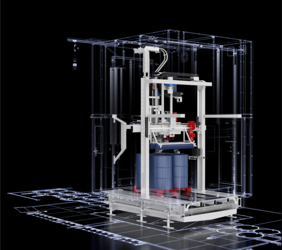
These systems must balance performance, safety, manufacturability, and long-term reliability, often under continuous or high-load operation. Industrial machines are complex assemblies of multiple moving parts that must interact without physical contact. For successful use in the field, engineers need to determine how these components move relative to one another while ensuring that no structural interference occurs over the full range of operation.
What level of precision is required for industrial machinery design?
Precision in industrial machinery design is application-dependent, but always critical. Engineers define acceptable dimensional variation using tolerances to ensure parts fit, move, and perform reliably under real-world conditions.
- Standard tolerances (e.g., ~±0.005–0.010 in / 0.127–0.25 mm) are common for general machinery components
- Tight tolerances (e.g., ±0.001 in / 0.025 mm or finer) are required in high-performance systems like aerospace or medical equipment
The key tradeoff:
- Tighter tolerances → higher cost, more complex manufacturing
- Looser tolerances → risk of failure, wear, or poor performance
That’s why modern machine design relies heavily on simulation and digital prototyping to validate motion, detect interference, and optimize tolerances before production—reducing rework and ensuring systems perform as intended.
What industries rely on industrial machinery design?
Industrial machinery design underpins nearly every production-driven industry, because machines are what enable scalable, repeatable output.
Key industries include:
- Manufacturing: assembly lines, robotics, CNC systems
- Construction & infrastructure: excavators, cranes, heavy equipment
- Agriculture: automated planting, harvesting, and processing equipment
- Energy & oil/gas: pumps, turbines, pressure systems
- Transportation & automotive: production tooling and vehicle systems
- Aerospace & defense: high-precision components and manufacturing systems
At a macro level, the machinery sector exists to enable other industries to produce goods, build infrastructure, and operate efficiently, making it a foundational layer of the global economy.
Designing industrial machinery at this level of complexity requires more than static CAD models. Engineers must understand how systems move, interact, and perform under real conditions, which is where motion analysis, kinematics, and interference detection become critical.
Advanced kinematics and motion in industrial design
As part of the industrial design process, engineering teams need to systematically address every component’s degrees of freedom. Where every unconstrained part has six degrees of freedom—comprising three linear and three rotational axes—designers need to use mathematical constraints to limit these movements and define the machinery’s physical boundaries and operational paths.
Beyond locking parts into fixed positions, managing motion requires designers to consider scenarios in which motion in one component drives a specific reaction in another, such as in gear sets or cam-and-follower systems. These relationships require a deep understanding of ratios and transitional geometry to guarantee that the digital model behaves like the physical hardware. For example, rotational-to-translational transformations are essential for modeling lead screws or rack-and-pinion actuators where linear positioning depends on rotational input.
Interference detection is also an important checkpoint during the assembly process, as manufacturing teams need to verify that moving parts do not occupy the same space at any point during their duty cycle. Static interference checks are common, but dynamic interference analysis is truly necessary for high-speed industrial equipment. This process involves checking for collisions as the assembly moves through its entire range of motion.
By identifying these issues in a virtual environment, engineers can adjust tolerances and geometry to accommodate thermal expansion, vibration, and operational clearances.
Validating machine performance with Autodesk Inventor
Using Autodesk Inventor, design teams can move beyond static modeling to create dynamic assemblies that simulate real-world conditions.
For example, designers can use Inventor to apply Joints and Constraints to define precise mechanical relationships. While standard constraints fix components in space, the Joint tool allows designers to define specific types of movement, such as sliders, cylindrical joints, or ball joints. This tool makes sure the assembly moves only within the intended physical parameters to guarantee a high level of functional accuracy.
Product teams can also use advanced motion constraints within Autodesk Inventor to model sophisticated mechanical transmissions. With the Rotation-Rotation constraint, designers can set precise gear ratios between spinning components to verify timing and synchronization. To model threaded components or linear actuators, designers can apply Rotation-Translation constraints to link angular movement to linear distance. These tools help engineers visualize the helical motion of a screw or the travel of a carriage so that designs are implemented correctly.
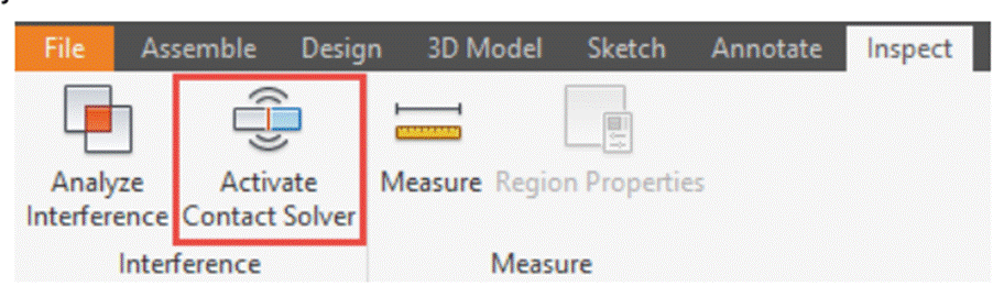
To address the challenges of physical contact and collision, development teams can use Inventor’s Contact Solver feature. This mechanism allows parts to behave as solid objects that stop upon collision, rather than passing through one another. Engineers can add specific components to a contact set to investigate how parts interact during operation. Using the Drive Constraint tool, manufacturing teams can then animate these relationships and record the motion for further analysis.
How Inventor supports design automation for custom machinery
One of the biggest challenges in industrial machinery design is managing customization. Many equipment manufacturers build products from a common platform but must adjust dimensions, components, layouts, or performance specifications to meet individual customer requirements.
This is where design automation becomes valuable.
Inventor includes iLogic, a rules-based design automation capability that helps engineers automate repetitive design tasks and rapidly generate configurable products. Instead of manually recreating assemblies, drawings, and models for every customer request, teams can define engineering rules that automatically adjust designs based on specified parameters.
Common examples include:
- Conveyor systems with different lengths and widths
- Material handling equipment
- Packaging machines
- Automation systems
- Custom production equipment
- Configurable machine assemblies
By reducing repetitive modeling work, design automation can help engineering teams respond more quickly to customer requirements while maintaining consistency across product lines.
For manufacturers that frequently create engineer-to-order or configure-to-order products, design automation can significantly reduce engineering effort and accelerate project delivery.
Engineering the future of industrial machinery
The ability to accurately model motion and kinematics is what separates successful designs from costly failures. By having access to advanced assembly techniques and interference validation in a single workflow, engineers can deliver more reliable and efficient industrial solutions. Autodesk Inventor offers all of the tools a designer needs to confidently push the limits of mechanical complexity.
Industrial machinery design frequently asked questions (FAQs)
Engineers model complex motion by defining mechanical relationships, such as rotation, translation, and synchronization directly within digital assemblies. In Autodesk Inventor, this is done using joints and motion constraints that mirror real‑world behavior, allowing designers to control how components move relative to one another long before physical hardware exists.
Kinematic analysis ensures that mechanisms move as intended across their full operating range, preventing timing errors, over‑constraint, or unintended motion. By validating kinematics early in tools like Inventor, teams can confirm gear ratios, actuator travel, and motion sequencing digitally, reducing the risk of failure during physical prototyping.
Each unconstrained component has six degrees of freedom, which must be intentionally limited to reflect real mechanical boundaries. Applying appropriate constraints defines how parts are allowed to move, ensuring the digital model behaves like the physical machine. Autodesk Inventor enables engineers to precisely manage these freedoms, improving functional accuracy and predictability.
Engineers use dynamic interference analysis to check for collisions as an assembly moves through its full duty cycle. Rather than relying solely on static checks, they simulate motion to identify where parts may intersect during operation. In Inventor, tools like animation, drive constraints, and contact‑based evaluation help reveal these issues early.
Digital simulations allow engineers to test motion, contact, and clearances under realistic conditions before manufacturing. By simulating component interaction, including stop conditions and physical contact tools such as the contact solver in Inventor, teams refine geometry, tolerances, and motion paths to avoid costly collisions and mechanical failures in the field.
Industrial machinery design software is used to create, simulate, document, and manage complex equipment and production systems. Common capabilities include 3D CAD modeling, automation design, engineering documentation, simulation, and collaboration tools.
Autodesk Inventor combines mechanical design, documentation, simulation, and design automation capabilities within a single engineering workflow.
When evaluating industrial machinery design software, manufacturers should consider:
-3D mechanical design capabilities
-Large assembly performance
-Design automation
-Simulation tools
-Manufacturing documentation
-Collaboration and data management
-Integration with factory planning workflows
The best solution depends on product complexity, team size, and engineering requirements.
Many machinery manufacturers build configurable products that require frequent engineering changes.
Design automation reduces repetitive work by allowing engineers to automate common design tasks, generate product variations faster, and maintain consistency across projects.
Inventor supports this through iLogic design automation.
Autodesk Inventor is commonly used for custom machinery design because it supports parametric modeling, configurable assemblies, engineering documentation, simulation, and design automation.
For organizations producing custom or configurable equipment, Inventor’s iLogic capabilities can help streamline engineering workflows.
Manufacturers can reduce engineering effort by:
-Reusing proven designs
-Standardizing components
-Automating repetitive design tasks
-Implementing configurable product models
-Using design automation tools such as iLogic
These practices help shorten design cycles and improve consistency.
Industries commonly using Inventor include:
-Industrial automation
-Material handling
-Packaging machinery
-Food and beverage equipment
-Process equipment
-Manufacturing systems
-Special-purpose machinery