Learn what design intent means in CAD, why it matters for parametric modeling, and how Autodesk Inventor helps engineers build stable parts, assemblies, and configurable products that update predictably.
Enhance Your Engineering Workflows
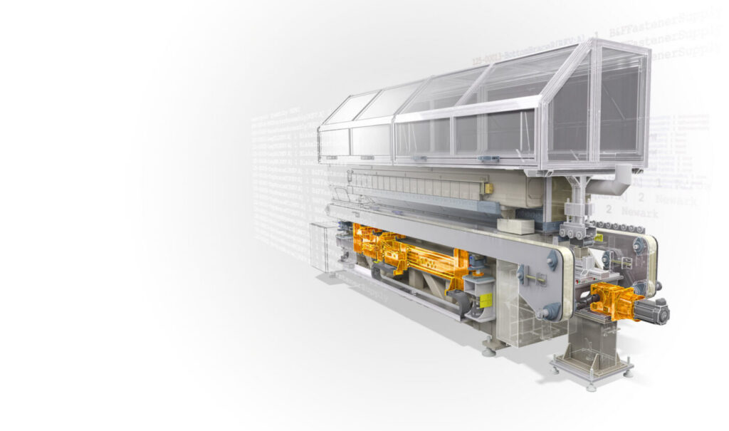
Precise, powerful, and ready for innovation with Autodesk Inventor.
A 3D model can be geometrically correct and still be a poor engineering asset. If a simple change causes sketches to flip, features to fail, assemblies to break, or drawings to fall out of sync, the issue is not just geometry. The issue is design intent. In parametric CAD, design intent is the way a model is meant to change over time. A well-built model is not only accurate today; it is also easy to update tomorrow.
That is why design intent matters so much in modern mechanical development. Teams are under pressure to deliver increasingly complex, customizable products faster, often with fewer engineering resources. At the same time, late design changes can ripple across parts, assemblies, drawings, and downstream manufacturing, creating rework and delays. Design intent is a practical way to reduce breakage, speed revisions, and make engineering knowledge reusable across a product line.
What is design intent in CAD?
Design intent is the logic that governs how a model responds to change. It determines which dimensions drive the design, which relationships must remain fixed, what ranges are valid, and what should not change at all. In practice, it means thinking beyond how a part is built to how it will be edited and maintained.
That intent is expressed through parameters, constraints, and clearly structured relationships that guide how the model behaves. It also requires anticipating change during the initial build, not reacting to it later. Parametric modeling extends beyond geometry into time, where future edits are considered upfront.
Many CAD failures are ultimately design-intent failures. A model may appear stable initially, but weak relationships, excessive projections, poorly constrained sketches, or undefined parameters become exposed as soon as changes are introduced. When constraints and parameters are applied deliberately, updates remain predictable. When they are not, even minor edits can destabilize the model.
Why weak design intent causes so much downstream pain
Problems with design intent rarely appear during initial modeling. They surface later, when a design is reused, handed off to another engineer, or revised under time pressure. At that point, unclear intent forces users to reverse-engineer how the model works, apply risky workarounds, or rebuild it entirely.
The same issues often begin at the sketch level. Underconstrained sketches allow geometry to shift unpredictably, while overconstrained sketches introduce conflicts. In both cases, poor sketch logic leads to fragile models. What starts as a small issue quickly scales into broken features, unstable assemblies, and inaccurate drawings.
As assemblies grow more complex, the impact compounds. A single unstable relationship can cascade across multiple parts, making updates risky and time-consuming. In these environments, design intent is not just about making a part editable, it’s about maintaining stability across an entire system.
The foundations of strong design intent
Strong design intent starts with structure. A well-organized model makes it clear what drives the design and how it should be modified. Relationships should be defined deliberately, parameters should be named and meaningful, and configuration logic should be explicit—not buried in the feature tree.
The first layer is sketch discipline. Fully constrained sketches behave predictably. Geometric constraints define relationships, while dimensions define size. Relying too heavily on dimensions without sufficient constraints often leads to instability.
The second layer is parameter strategy. Named parameters allow designs to be driven by clear, reusable values instead of fixed numbers. When key variables are easy to identify and adjust, the model becomes easier to control, adapt, and reuse across variants.
The third layer is dependency management. References and relationships should be applied carefully to avoid unnecessary risk. Overly complex or fragile dependencies, especially those tied to geometry likely to change, can quickly break as the design evolves. Models should also be built with realistic value ranges in mind, so they remain valid across expected changes.
Design intent is communication, not just modeling
Design intent is not just about how a model functions. It’s about how clearly that behavior is communicated to others. A model should not require interpretation each time it’s edited. Instead, it should expose its logic through clear parameter naming, structured relationships, and visible control points.
When the logic behind a design is easy to understand, teams spend less time troubleshooting and more time improving the product. Conversely, models that require trial and error to modify do not scale well across teams or product lines.
How Autodesk Inventor supports design intent
Autodesk Inventor supports design intent by giving engineers direct control over how models behave, not just how they look. Through parametric modeling, named parameters, and structured feature histories, designs can be built around clear, reusable logic instead of one-off geometry. Tools like iLogic extend this further by allowing rules, configuration controls, and driven values to be embedded directly into parts and assemblies, making design behavior explicit rather than implied. Combined with associative drawings and BOMs that update automatically, Inventor helps ensure that intent carries through from initial concept to downstream deliverables, so changes remain predictable, and designs can scale without breaking.
Ultimately, design intent determines whether a model remains useful after the first revision. It turns a static representation into a flexible, reliable engineering asset. Models built with strong design intent are easier to update, less prone to failure, and more effective for reuse, making them essential for managing complexity in modern product development.
Design intent in CAD is the logic that defines how a model is supposed to change over time. In Autodesk Inventor, it includes the parameters, relationships, and rules that determine how a part or assembly should be edited and updated predictably.
Design intent is important because Inventor models are parametric. If sketches, parameters, and dependencies are not structured deliberately, even small edits can cause geometry to shift, features to fail, or downstream assemblies and drawings to break.
You capture design intent in Inventor by fully constraining sketches, using named user parameters, defining relationships clearly, documenting important values with comments, and using iLogic when models need rules, forms, or configurable behavior.
Model parameters are created automatically when features or dimensions are added. User parameters are created intentionally, named for reuse, and are better suited for defining top-level design intent
iLogic helps communicate design intent by embedding rules directly into Inventor part, assembly, and drawing documents. It can drive parameter values, define component behavior, and present forms that show users exactly how a model is meant to be changed.
Yes. Autodesk Inventor supports configurable products through rules-based design, configurable forms, and iLogic-driven assembly logic. Autodesk’s training materials show iLogic controlling parameters and even adding or removing components to generate different configurations in a single assembly.
Sketch failures after a parameter change usually happen because a dimension equation becomes invalid, referenced geometry no longer exists, or constraint logic conflicts with the new values. Parameter-driven sketches need range-safe logic to remain stable across expected changes.
Inventor supports top-down design through assembly-level parameters and iLogic rules that can drive subcomponent values. Autodesk’s training shows assembly parameters automatically updating component widths and other dependent settings across the design.
Good design intent helps keep drawings and BOMs reliable because Inventor supports associative documentation and synchronized outputs. When the model changes predictably, connected drawings and parts lists can stay aligned with less manual rework.
The strongest Inventor workflows for preserving design intent include parametric part modeling, assembly constraints and motion, rules-based automation with iLogic, BOM/data-quality workflows, and associative drawings and documentation.