Every year, millions of holiday lights go dark around the world for one critical lesson—to teach you the difference between series circuits vs parallel circuits! Let’s get into the similarities and differences between the two.
First, the basics
Before we dive into the difference between series circuits vs parallel circuits, let’s go over some basic terms that we’ll be throwing around.
- Current: Electricity has work to do, and when the electrons are flowing around a circuit, that’s current at work.
- Circuit: If it’s a closed, continuous path, then electricity will flow on it. Along this path, electricity can do a ton of amazing things, like power your smartphone, or send humans to space!
- Resistance: This is what electricity encounters when it flows along physical material, whether that’s a copper wire or a plain old resistor. Resistance restricts the flow of electric current.
Below you’ll find an image of a simple circuit, which includes a battery, a switch, and a light bulb.
The season of series
Say you have a strand of lights, connected one after the other. If you viewed this in a circuit, it would look something like this:
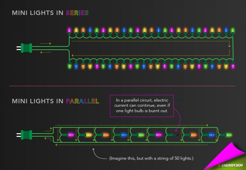
When we plug our strand of lights into an outlet, what will the current do? Let’s follow the flow:
- Powering it up: When we plug our holiday lights in, the current starts flowing from our wall outlet.
- Flowing along: It then moves along the strand of copper wire and through our holiday light, making it shine brightly.
- Coming home: When our current reaches the end of our strand of lights, it heads for the ground to get some rest, and so the cycle continues.
It doesn’t matter what kind of components you place in a series circuit, you could mix and match capacitors, resistors, LEDs, and a bunch of holiday lights together and the current would still flow the same, from one part to another.
Now, this is where holiday lights tend to have their downfall. What happens if you yank out one of those bulbs in your strand of lights? If your lights are anything like ours, then all of them turned off! Why is this? Think about it, if the current is flowing from light to light, and you disrupt that connection, then you’re cutting off the path on which the electricity is trying to flow. This is called an open circuit.
Current and resistance in series
There is a fundamental law of the universe to remember for how current and resistance work in a series circuit:
The more work (resistance) that a series circuit does, the more its current will decrease.
Makes sense, right? As you add more resistance to a circuit, like some holiday lights, or even a resistor, then the more work for your circuit has to do. Let’s say you take the circuit we introduced at the beginning of this blog that had one light bulb. Now, what would happen if you added another light to this circuit? Will both bulbs shine as brightly? Nope. When you plug in that second bulb, both will get equally dim, because you have added more resistance to your circuit, which decreases the flow of current.
But how do you go about figuring out how much resistance you have in a series circuit? You just add all of the different resistance values together. For example, in the circuit below we have two resistors, each being 10k Ohms. To get the total resistance in this circuit, just add all of the numbers together. That’s 10k + 10k, which comes to 20k Ohms of total resistance.
And what would your current be in this circuit based on that amount of resistance? Here’s how you can figure it out.
- Using our trusty Ohm’s Law Triangle, we get the equation we need to use: I = V/R, or Current = Voltage divided by Resistance.
- Plugging in the numbers that we know, we get I = 10V/20k. 0.5 milliamps (mA) are flowing through our circuit!
- What if we took out one of the resistors? Now our equation is I = 10V/10k, and we’ve increased our current to 1 milliamp (mA) by reducing our resistance.
Working in parallel
Now, wouldn’t it be great if you pulled out one of the bulbs in your strand of holiday lights but the rest of them stayed on? If your holiday lights were all wired in parallel, then this is exactly how they would behave!
In a parallel circuit, imagine your strand of lights all connected together. But instead of each bulb being connected one after the other, they are all connected separately, in their circuits like in the image below. As you can see, each bulb has its own mini circuit that is separate from the other, but they all work together as part of a larger circuit.
But how does the current flow in this kind of circuit? It doesn’t just follow one path; it follows all of them, all at the same time! Here’s why this is awesome. Imagine that you yank out one of the bulbs in this type of circuit. Rather than stopping your whole holiday light operation, the rest of the circuit will keep on flowing because each light is not dependent on the light before or after it for its source of electricity.
Current and resistance in parallel
When a circuit is wired in parallel, current and resistance start to do some strange stuff that you might not expect, here’s what you’ll want to remember:
In parallel circuits, as you increase the resistance, you’ll also increase the current, but your resistance gets cut in half as a result.
Wait, what? That sounds crazy! But think about it regarding your holiday lights. As you add more colorful lights to your circuit, then you need to draw more current to power all of those lights, right? And so a magical thing begins to happen, the more lights that you add, the higher your current climbs, but that increased current has an opposite effect on your resistance.
This might be a bit tough to wrap your mind around, so let’s go through a simple example. Say we have a 10V battery source and two 10k resistors that are connected in parallel. Now, since each resistor has its own circuit, we need to figure out how much current each will use:
- Going back to our Ohm’s Law Triangle, we know the equation we need to use is I = V/R, or Current equals Voltage divided by Resistance.
- And plugging our numbers in, we get I = 10V/10k, which comes to 1mA. But that’s only one of the two resistor circuits; we now need to double the current to get our total for the entire circuit, which is 2mA.
- Now, what happens to our resistance at two amps? We can use Ohm’s Law to figure it out with R = V/I, which comes to R = 10V/2mA = 5k Ohms. Because we doubled our current, our original 10k resistors are now only doing half the resistance!
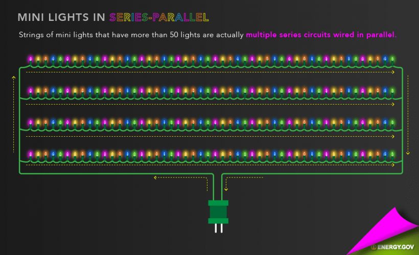
How your holiday lights really work
So how do those holiday lights of yours really work? Here’s a hint – they are neither 100% series or 100% parallel, they’re both! Those smart engineering elves decided that the most efficient way to make your holiday lights work is to connect several series of lights together in parallel.
Here’s why this series/parallel hybrid is great—if you yank out one light, only one section of your lights will turn off, not all of them. This is because you have only affected one of the series circuits in your larger parallel circuit. But why didn’t the engineering elves just make all the lights in parallel? That would require a ton of wires, and Santa needs to watch his manufacturing costs just like us!
But wait, you might remember that one year when you had a light burn out, but the rest of your lights kept working, what happened there? You can thank this little magic trick on what’s called a shunt. This little device allows current to continue moving through a circuit even after the light burns out. How so? Let’s take a closer look at one of your holiday lights below:
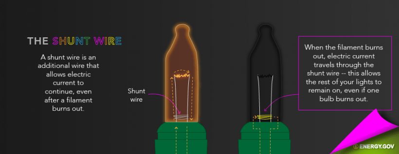
See that wire that’s wrapped around the bottom part of the light? That’s the shunt, and it has a coating on it that prevents any electricity from flowing through it while the light is working properly. But when the wire at the top burns out, the increase in temperature melts the coating off of the shunt wire, allowing electricity to keep passing from one terminal to the other of the light, so your holiday lights keep working!
Now you know: Series circuits vs parallel circuits
There’s your present for the year! You now have some newfound knowledge about series circuits vs parallel circuits and how they work together to make your holiday lights shine brightly.
Circuits wired in series are the easiest to understand, with current flowing in one continuous, smooth direction. And the more work you have a series circuit do, the more your current will decrease. Parallel circuits are a bit trickier, allowing multiple circuits to connect while operating individually as part of a larger circuit. Because of this interesting connection, as you increase the resistance in a parallel circuit, you’ll also increase the current!
And if you’re still lost, then perhaps you have hit your limit on eggnog. Ready to design your own circuits today? Try Autodesk Fusion for free today.