Discover enhanced data management, asymmetric fillets, upgraded electronics, a new hole template editor, advanced turning capabilities, and more in the November 2025 Fusion update.
Table of Contents
- Minor Updates
- Highlights
- Usability
- Data Management
- Design
- Drawings
- Electronics
- Manufacturing
- API
- Insider Program
- Release Notes
Minor Updates
Our latest minor updates brings several important fixes and improvements to enhance your experience. Click to learn more.
v.2605.1.52 – December 8, 2025 (Minor Update)
Usability
- Improved stability while loading the cache for properties contents.
Design
- Fixed an issue where the Sparkle icon in Sketch Fixer thumbnails appeared blurry in Windows environments.
- Improve stability in component tree operations.
Electronics
- Resolved an issue where the Push to 3DPCB option was missing under the Switch command in a Fusion 2DPCB document.
- Improved performance when saving an electronics design.
Manufacturing
- Improved stability in CAM and Drawing workflows.
- Resolved an issue where the ‘Clockwise Spindle Direction’ checkbox was incorrectly visible in the Turning Tools library.
- Improved toolpath generation speed by addressing performance issues in the ‘Updating’ state.
- Resolved an issue that caused toolpaths referencing mesh bodies to fail to calculate in certain cases.
- Enhanced performance by optimizing runtime evaluations to reduce excessive processing time.
v.2605.1.39 – November 20, 2025 (Minor Update)
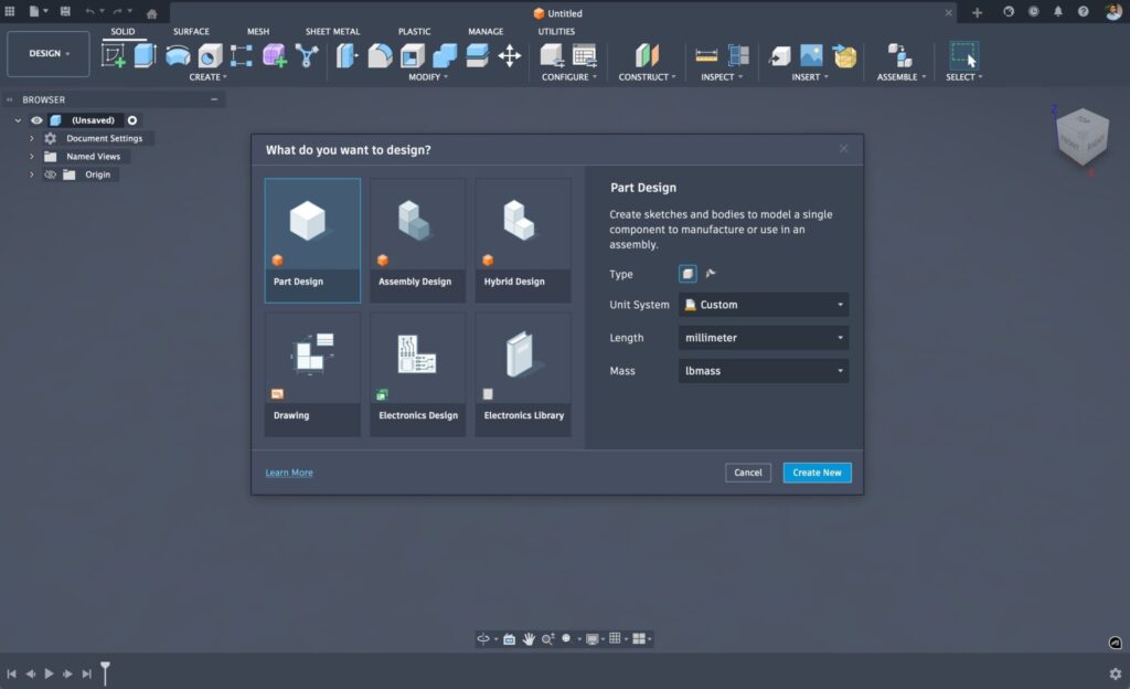
New Intent Driven Design Preview
Preferences > Preview Features > Parts and Assembly Workflow
Experience the new Intent-driven Design Preview in Fusion, designed to simplify your design process with clear pathways for starting projects through Part, Assembly, or Hybrid workflows. This preview eliminates the confusion between bodies and components, boosting your design efficiency and enhancing collaboration. Whether you’re focusing on single parts, structuring detailed assemblies, or maintaining a flexible hybrid approach, the Intent-driven Design Preview offers smarter organization, and better teamwork capabilities.
Learn more about Intent Driven Design.
We value your feedback! Share your thoughts in the Fusion Insider Program and help us shape the future of Fusion.
Resolved Issues
Drawings
- Resolved an issue where Drawing commands did not work when launching new document prompt from the Home tab.
- Resolved a synchronization issue between Design and Drawings that caused drawing views to experience display issues after design changes.
Electronics
- Resolved an issue where renaming a component in the schematic caused ERC to fail.
- Resolved an issue where the signal layers were ordered incorrectly in the drop-down menu.
Manufacturing
- Improved stability when using tool selection in Toolpaths.
- Resolved an issue with drilling using a 90-degree chamfer tool where the flute height is the same as its radius.
v.2605.1.18 – November 9, 2025 (Minor Update)
Data Management
- Resolved an issue where some filters and tooltips were not localized in the History Panel.
- Resolved an issue where the Bill of Materials (BOM) encountered an error (indicated by a tipped over cup) if opened “too quickly” after a design was imported or restored.
- Resolved an issue where an incorrect
assemblyRef targetTimeoccurred when creating a new external component and saving in Fusion. - Resolved an issue causing continuous loading of physical properties for the root and errors for children in case of a circular reference.
- Improved stability for Hometab workflows.
Design
- Resolved an issue where AutoConstraint crashed when configuring a command launched with AutoConstraint.
- Improved stability during the application launch.
- Resolved an issue where deriving sub-components from different linked component instances was not possible. Note: This fix does not apply to multiple instances of local components.
Electronics
- Resolved an issue where the
layerCLI command could not be added when the current drawing didn’t have extended layers.
Manufacturing
- Improved stability when calculating toolpaths.
- Improved stability when changing the number of copies using arrows in Duplicate Components.
Highlights
v.2605.0.97 – November 5, 2025 (Major Update)
We’re excited to introduce the latest Fusion update, packed with powerful enhancements and new features designed to elevate your design and manufacturing processes.
Whether you’re streamlining data management, experimenting with new asymmetric fillets, or pushing the boundaries of manufacturing with cutting-edge turning capabilities, this update has something for everyone.
Let’s jump into the highlights and see how these enhancements can help you work smarter and achieve more.
Usability
- “Match OS” is now the Default UI Themes Setting
- New Preference to Control Modeling Canvas’ Exposure
- Enhanced View Cube Navigation
- Enhanced Component Filtering
Data Management
- Physical Properties in Bill of Materials (Collaborative Editing Hubs)
- Improved Property Management (Collaborative Editing Hubs)
- New Trash While Referenced
- Enhanced Group Management
- Numerous Home Tab Improvements
Design
- New Asymmetric Fillet
- New Bounding Solid
- New Center Constraint Type
- Enhanced Sketch AutoConstrain
- Enhanced Decal Accuracy and Control
Render
- Enhanced “Snap To” Geometry Experience
- New Move Command
Drawings
- New Limits and Fits
Electronics
- Improved Update Mechanics between 2D & 3D PCB
- New BOM Experience
- Renumber Reference Designators for Schematic and 2D PCB
- Search for Libraries by Component Name
- Scan Hub for Missing Libraries
Manufacturing
- New Hole Template Editor
- Enhanced Machine Over Holes/Pockets
- New Clearance Geometries and Visualization
- Multi-axis Drilling Operations (Manufacturing Extension)
- Numerous Turning Enhancements
- Numerous Enhancements to Additive Manufacturing
Usability
“Match OS” is now the Default UI Theme Setting
Back in September we launched a new “Match OS” setting that automatically aligns your Fusion theme with your device’s system mode. This made it so if your laptop is in dark mode, Fusion will follow suit — no clicks required. As of this update “Match OS” is now the default UI Theme setting.
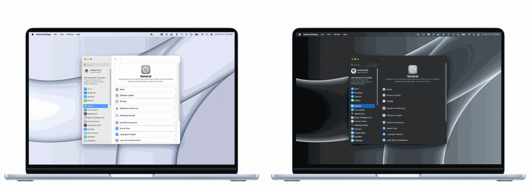
Learn more about Fusion UI themes.
New Preference to Control the Modeling Canvas’ Exposure
Preferences > Material > Exposure
Previously, we increased the default brightness of all canvas environments. While some appreciated the change, others found it too bright. In response to your feedback, there is now a slider that enables adjustment of the canvas lighting in the modeling canvas.
Enhanced View Cube Navigation
The View Cube orbit experience has been improved to keep your focus area (selected geometries) in view during orientation changes.
Previously, when you clicked on a View Cube face to change your perspective, the area you were working on would often move out of frame, requiring you to zoom or pan back to continue your work.
Now, when you have geometry selected, the View Cube will automatically orbit around the center of your selection, keeping the selected objects in view during orientation changes. When nothing is selected, the View Cube maintains the familiar behavior you’re used to, ensuring no disruption to existing workflows.
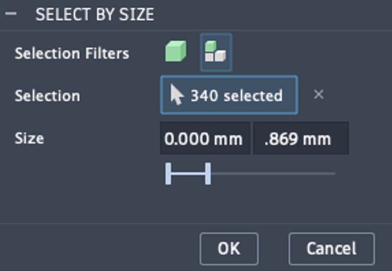
Enhanced Component Filtering
Select > Selection Tools
The Select by Size dialog now includes a body/component choice option, allowing you to select whether to work with individual bodies or entire components.
To use this functionality, access the “Select by Size” tool from the Selection Tools menu. In the dialog box, you’ll now see Selection Filters to choose between selecting bodies or components. Select your preferred filter based on whether you want to remove individual bodies or entire components and then set your size criteria and apply the selection.
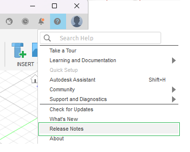
“Release Notes” Link Now Available in Fusion Help Menu
We’re excited to announce the addition of “Release Notes” to the Help Menu. This feature provides you with easy access to detailed technical information surrounding the latest updates to Fusion, Fusion web client, and more.
Performance
We’re excited to share that our latest update brings significant improvements to make your design work smoother and faster. Here are some of the key enhancements:
- Sketch: Resolved freezing issues and dramatically improved the speed of adding lines to existing sketch chains.
- Timeline: Playback of certain design files is now up to 60% faster.
- Edit In Place: Experience improved responsiveness when creating features like Extrude, Hole, Rib, Boss, and Lip.
- Drawing: Faster saving, reopening, and handling of large assemblies, with file sizes reduced and operations like mass calculation sped up.
- Command Launch: Commands like Arrange, Move, and Remove execute much faster with pre-selected bodies.
- Window Selection: Significant speed improvements on both Windows and Mac when performing window selections in complex designs.
Note: These improvements are based on datasets provided by our customers, and the performance gains can vary depending on the specific dataset.
Data Management
Autodesk Fusion is the connected platform for teams, unifying people, data, and processes so you can move faster, reduce errors, and innovate with confidence and this November brings even more.
Learn more about Collaborative Editing (CE) enhancements.
Data:
We’ve enhanced the Fusion data model, including Bill of Materials (BOM) physical properties, experience improvements – helping you build more intelligence into Fusion models.
Improved Property Management (Collaborative Editing Hubs)
We’re making it easier to manage properties. Hub Admins can now break up large Shared Part Number groups into standalone parts with just a few clicks; each separated model carries its own part number, properties, and BOM, reducing unintended coupling and clarifying change control.
Learn how to separate a shared part number.
We’ve also localized key component property descriptors—Component, Project, and Summary—so teams can view and manage fields in their preferred language. The result: clearer ownership, more accurate BOMs, and a smoother experience for global teams.
Strengthened Bill of Materials (Collaborative Editing Hubs)
You can now expose physical property columns in BOM to help you facilitate inventory management, calculate total assembly weight, and estimate shipping costs. Admins can control visibility with a hub level toggle and expose fields like mass, volume, area, length, width, and height with automatic rollups and totals based on assembly associations.
Values respect the same decimal precision you see in Fusion’s canvas for consistency across design and downstream reporting. We’ve also added density to the physical properties set, calculating and displaying it for both components and assemblies to support more accurate material planning.
Learn how to enable physical properties.
More Powerful Data Management
We’re making everyday data work faster and more predictable. Copy/Paste as New now copies properties from the source to the new component with more intuitive part number handling.
Working with large, distributed models is simpler, too. Have you ever seen a message saying you weren’t able to delete a model that was referenced in a distributed design? Fusion now flags those references, explains the consequences, and lets you safely proceed with deletion from desktop or web. And when reviewing history in the web client, Open in Desktop is available so you can resolve and manage your designs directly in the desktop application.
Note: the above items are available in Hubs with collaborative editing enabled.
We’ve also improved data access in the desktop client and in the web browser. In the Fusion Home Tab, you can now cache designs for offline access and create new versions / milestones. Additionally, we made it easier to access your data where you want it. From the Fusion Home Tab, you can now open a folder directly in the Fusion web client. In the Fusion web client, you can export drawings for review, sharing, and release. This includes drawings that contain new extended properties in the parts list and title block.
Trash While Referenced
Fusion gives you the choice of working in one model or with distributed designs with external references. We’re seeing more adoption of external references and have heard your feedback on wanting more consistent and robust deletion when using external references.
Previously, if a design file was referenced by any latest or historical drawings, designs, or manufacturing-related files, in many cases it could not be deleted in order to keep models intact.
Now, when you attempt to trash a referenced design, you will be informed about the reference, provided with a description of what moving to trash entails, and given the option to proceed with the move to trash in Fusion on your desktop and in the web.
People:
We’re making admin simpler and security stronger. We are also making it easier to collaborate by allowing you to manage groups in one place for your entire Hub and introducing a new ability to Merge Hubs.
Enhanced Administration of Members and Groups for Fusion Hubs
We’re excited to announce new enhancements to Autodesk Fusion hub administration designed to make managing your collaborative environment smoother than ever. The updated Members management experience offers intuitive tools for inviting new members, assigning hub roles, tracking member status, and viewing group participation.
In addition, we’ve rolled out a brand-new Group administration feature that empowers admins to easily create and manage groups, as well as oversee group membership, from a single, centralized administrative experience. These improvements give administrators greater control and visibility, making it easier to organize teams within Fusion.
Learn more about groups.
New Hub Merge (Collaborative Editing)
A hub merge moves all data—designs, drawings, projects, folders, and users—from one hub into another. This is helpful when multiple teammates have created separate hubs and want to consolidate for better collaboration. Only hubs using collaborative editing can be merged, so all hubs must be upgraded to support collaborative editing before merging.
Learn how to merge hubs.
Process:
Fusion Manage has powered part numbering, release, and change management in Fusion for several years. We have strengthened this integration over the past few months and dramatically expanded PLM capabilities available in the platform.
Introducing the Template Library
The Template Library is a one-stop shop for best practices, ready-to-go workflows, and reusable PLM process frameworks. It’s designed to take the guesswork out of configuring your PLM environment. Whether you’re just getting started or looking to optimize existing processes, you’ll find a rich selection of templates to jumpstart your journey.
With a wide array of business processes covered, you’ll find several templates that can be used to manage product-related processes upstream of engineering, such as product portfolio management, requirements management, and new product introduction or others downstream, such as quality management and supplier collaboration.
Each template is pre-built but also fully customizable, so you can tweak it to fit your unique needs without starting from scratch. The template library can be found within the Fusion Manage Extension web client’s main menu; simply navigate to PLM Settings > Template Library.
Design
New Asymmetric Fillet
Design > Solid > Modify > Fillet
We are excited to introduce Asymmetric radius type for both standard and Rule Fillet. Specify two unique radius values to apply an asymmetric fillet along the selection.
Key Features include:
- Dual Radii: Specify two unique radii based on your curvature requirements and easily flip the values per selection set.
- Fine-Tuned Control: Achieve precise control over edge curvatures or selected junctions using both Fillet and Rule Fillet options.
- Configurable Aspect: You can configure each unique radius value independently, either in Configuration Mode or on the fly.
- Compatibility: Subsequent operations like Press Pull or Draft preserve the shape and values of these fillets, ensuring integrity in the parametric model. Fully compatible with downstream modeling operations, including EIP mode and derived models.
- Modification Capability: You can edit existing fillets and change the radius type to Asymmetric.
- API Support: Full API support is available for scripting and add-ins, enabling comprehensive workflow integration.
Learn more about Fillets.
New Center Constraint Type
Design > Assembly > Relationships > Constrain Components
Assembly Constraints just got better with the new Center constraint type. This new feature lets you center one component between two faces of another component. Essentially, this lets you align geometry to a midplane without creating construction geometry. Your geometric selections determine how the components are positioned relative to one another.
The selections don’t have to be parallel, giving you greater flexibility in creating your assemblies.
Learn more about assembly constraints.
AutoConstrain Enhancements
Design > Sketch > Constrain > AutoConstrain
AutoConstrain in Sketch now detects and corrects geometric inaccuracies in your sketch, such as small gaps, off-axis lines, near-tangent arcs, and more. It provides a new results card with the corrected sketch. A special icon distinguishes corrected sketches, which only appear if geometric corrections are needed.
Use the slider to adjust the tolerance or specify unique values for each sketch constraint type: horizontal/vertical, tangent, parallel/perpendicular, coincident, and concentric. AutoConstrain ensures points, lines, and arcs within these limits are accurately aligned.
You have full control over the results. Customize tolerances individually via the tolerance box or adjust all simultaneously with the slider. This flexibility guarantees precise corrections, enhancing design accuracy and efficiency.
Visibility Control Command in Edit In Place
Introducing Context Visibility, a powerful new feature within the Edit in Place mode that lets you manage the visual effects of components with precision. Now accessible from the Edit In Place toolbar dropdown via the “Visibility Control” command, this feature enhances clarity when working on complex designs.
Key Features include:
- Visibility Toggles: Easily switch visibility for both Reference and non-Reference Objects.
- Opacity Control: Adjust opacity with two separate sliders for Reference Objects and non-Reference Objects.
- Visual Style Options: Choose from visual styles like Shaded, Wireframe, Shaded with Visible Edges, and Wireframe with Visible Edges for non-Reference Objects.
- Component Color Override: Enable this option to color Reference Objects in purple and non-Reference Objects in yellow, while EIP components retain their normal colors.
These visibility settings are maintained throughout your EIP session and revert to normal upon conclusion. The system remembers your last EIP visibility settings across different Fusion sessions, allowing you to easily reapply them when you start a new EIP session without having to reconfigure from scratch.
Learn more about the Visibility Control Command in Edit in Place.
New Bounding Solid
Now with the new Bounding Solid tool you can create a solid component around selected components or bodies. The resulting Bounding Solid- a box, cylinder or tube- is a standalone solid component that can be used for measurement, or to represent the stock volume for manufacturing, or as a base for an outer shell design.
Bounding Solid offers benefits when used as a stock volume for manufacturing; it can be used in an assembly (for example in a vice or fixture) and for general modeling operations (for example to create soft jaws).
Enhanced Configuration Properties Table (Collaborative Editing)
In July, we enabled the workflow that lets you configure properties for internal components in a Configured Design within Collaborative Editing hubs. In this release, we’re adding some fit and finish support to the workflows in the Properties tab of the Configuration Table.
You can now Show/Hide individual property columns to tailor the view to display only the Property data you need to see.
Retain Wireframe Data when Importing CAD Models
When CAD models are imported, wireframe data (i.e. discrete curves not on a surface) are now retained and placed in a sketch, for potential use in downstream activities, for example, in the manufacturing workspace, engraving or constraining 5-axis machine tool motion using a point or curve.
Enhanced Mesh Face Groups Support
Fusion now supports the import and export of meshes with Face Groups. Previously, Face Group data was not read during import or included in exported 3MF files. To export a 3MF with Face Groups, simply use the “3MF Scene Export” command from an additive setup in the Manufacture workspace. When importing a 3MF with Face Groups, use the “Insert Mesh” command in the Mesh tab of the Design workspace.
Sheet Metal
Flange Icon Separation
Design > Sheet Metal > Create > Flange
Last release we separated Lofted Flange from a Normal Flange to allow for better timeline and toolbar management. In this release, we have further separated out the Flange tool to improve workflows across the board.
Base, Edge and Contour Flange types now have unique timeline icons and titles in forward creation and edit dialogues. The forward creation workflow remains unchanged allowing you to discover which type of flange is appropriate.
Flange Profile Regeneration
We have improved the way sheet metal flanges are updated. Now, any changes you make to a profile will dynamically update the flange. Previously, adding or removing segments from the profile could cause issues with the feature, but that’s no longer the case.
Learn more about Sheet Metal Flanges.
Render
Enhanced “Snap To” Geometry Experience
Previously, when you moved the ground plane in renderings and snapped to model geometry, there was no visual feedback showing what you were snapping to. Now, when you snap the floor location to model geometry, you will see highlights indicating where you are snapping to. Simply hover to see the highlighted face and click to snap to it.
New Move Command in Render Workspace
In the Render workspace, you can now access the “Move” tool directly from the Setup panel to adjust your component positions. This eliminates the need to switch back and forth between the Render and Design workspaces just to reposition components.
Decal
Improved Decal Functionality
Design > Solid > Insert > Decal
Decals now respect the precise dimensions embedded in the image files, preserving the original dimensions, which is especially valuable when working with images created in external art programs where specific dimensions are defined. With the “Keep Aspect Ratio” option, decals maintain their intended proportions, ensuring that the images are represented correctly. Additionally, you can input exact sizing for the Decal image, giving you precise size control over your designs.
Learn more about Decals.
Know when a Decal is placed on the Inside Surface
When decals are placed on the inner side of surfaces, they are unable to render properly, making it a bit confusing when you expected to see the decal, but it instead appeared invisible. Fusion now lets you know when you attempt to place a decal on the inside surface of a model. Helping you understand why a decal might not be visible and guiding you to select the correct (outer) surface for proper decal placement and rendering.
Learn more about Decals.
Drawings
New Limits and Fits
Limits and Fits are now available in drawings. Simply edit a dimension and select a ‘Fit’. Choose a Hole/Shaft basis system, ‘Type” (Clearance, Transition or Interference), and the dialog will show preferred fit. You can even pick a custom fit and set how the tolerance is displayed.
Tip: Use “Match Dimension” to copy the modified tolerance between dimensions; the tolerance will update based on the geometry and the preferred fit.
Electronics
Improved Update Mechanics between 2D & 3D PCB
A key strength of Fusion is cross-discipline data management, where it is crucial to ensure that the 2D & 3D PCBs are kept up to date with each other not only within the Electronics contexts but downstream in the assembly documents like mechanical enclosures. Today, keeping these assets up to date with each other is unnecessarily cumbersome and error-prone, running the risk working on out-of-date data.
In this update, we’ve re-aligned this update mechanism to the familiar ‘pull’ update system present in the rest of in Fusion. This not only ensures no data clashes / merge conflicts but also introduces the ability to receive PCB changes (saved 2D PCB updates) directly within your chosen context (either a mechanical assembly or your 2D PCB) without having to manually regenerate the 3D PCB.
New BOM Experience
We have reimagined and modernized our BOM experience to allow for a more cohesive experience. Within this update you will find:
- Dynamic BOM Viewing: You can now view the Bill of Materials (BOM) contextually within the design file, with live updates. This eliminates the need for manual document saves to reflect changes.
- Enhanced Sorting & Grouping: BOM line items can now be sorted and grouped by reference designator or individual components, allowing for more efficient organization.
- Customizable Views: Display selected attributes as columns, including custom attributes, and hide/show columns with preferences that persist across sessions.
- Cross-Selection: Cross-select items between the BOM and canvas. For example, selecting a line containing R1-R3 will highlight R1, R2, and R3 on the canvas.
- Export Options: Easily export the BOM to Excel, CSV, and text formats using the existing BOM export experience.
Note: Existing BOM ULP can still be called programmatically, ensuring that no ULPs are disrupted.
Renumber Reference Designators for Schematic and 2D PCB
We’ve introduced a native ability to renumber reference designators (the reference designators are always synced between Schematic & 2D PCB), replacing our ULPs. This update includes all the features of the existing ULPs, plus additional enhancements for an improved experience. For example, you can now execute renumbering based on selections, specific sheets, or certain hierarchies.
Search for Libraries by Component Name
In the library manager, you can now enter the names of components you are looking for and see all publicly available libraries that contain the component. Simply activate the library and the components within it are ready to use in your designs.
Scan Hub for Missing Libraries
Previously, finding libraries to use within your current hub was a tedious process. You had to manually search for accessible libraries and open them to register them for use in Fusion Electronics. Now, the Library Manager includes a new option to scan all of your folders in your current hub and automatically import any missing libraries.
Additional Electronics Updates
Streamlined Component Authoring
In the library editor, new toolbar buttons and a sleek new design will help to speed up and simplify your process of creating custom components.
Add-in Manager now available in Electronics workspace
Add-in Manager for integrating and managing add-ins like SnapEDA, Ultra Librarian, and Avnet is now available directly within ECAD workspaces.
Manufacturing
Machine Over Holes/Pockets
We’ve expanded the “Machine Over Holes/Pockets” feature to support all 3D toolpaths that use Avoid Machine Surfaces. Previously, this was only available for Geodesic and Flat toolpaths. For drive surface driven toolpaths like Blend, Flow, and Geodesic, you can find the option on the Geometry tab under the Geometry section. For other toolpaths, it’s located on the edit form of a surface group in the Avoid Machine Surfaces table.
When you select this option, all surfaces in the group will be capped, meaning any holes or pockets in these surfaces will be automatically machined over by the toolpath, eliminating the need to define extra capping surfaces in Fusion.
Note: There are some limitations to be aware of: Flow toolpaths only cap holes/pockets intersecting a single machining surface, whereas other toolpaths support capping across multiple surfaces. Additionally, only closed holes/pockets will be machined over, meaning the selected surfaces must completely surround the hole or pocket.
New Hole Template Editor
A new Template Editor has been introduced for hole templates. This not only allows templates to be edited via the UI, it also significantly expands the definition of a hole signature. This allows you to create much more specific templates than before.
As of this update you can now interactively add Cylinder, Cone and Torus segments to build a hole signature. The dimensions of these hole segments can be set to be specific, within a given range or any size. A graphical preview of the hole signature is shown on the UI.
Hole segments can optionally be assigned a specific color in the template, such that when Hole Recognition is used the template will only match holes on the model with that color. Similarly, Cylinder segments can optionally include a specific thread designation to only match holes on the model with the same thread. Furthermore, Cylinder segments can specify to match using either the modelled diameter or Product Manufacturing Information (PMI). When PMI is used, both the diameter and tolerances can be included in the signature.
The Template Editor has tools to pick a hole signature directly from the model and to preview which holes on the model currently match the signature.
Hole templates can also be given a priority value. This allows you to indicate which template you would prefer to match a hole if there are multiple matching templates. For example you could choose to give a more specific template a higher priority and a more general template a lower priority.
The Template Editor also allows you to add, remove, reorder and edit operations used by the template. There are new options to specify which tool a template operation should use, including the ability to choose a specific tool for that operation.
Trim Enhancements (Manufacturing Extension)
When applying the Trim modification using a polygon, you can now choose to project the polygon onto the nearby surfaces instead of through the entire part. In this projection, only the visible sections of the toolpath within the polygon are considered ‘inside’; the rest of the toolpath will be considered ‘outside’. This enhancement allows you to make precise modifications exactly where needed, ensuring that other areas remain unaffected.
Create Selection Set in Avoid Machine Surfaces (Manufacturing Extension)
You can now right-click on a surface group in the Avoid Machine Surfaces table and Create Selection Set. This will copy the surface group and create a new selection set in the browser containing the copy, with the same name as the original surface group. The new selection set is independent of the original, so there will be no associative behavior. This feature, combined with the existing ability to add a selection set to the Avoid Machine Surfaces table, gives you the ability to share surface groups between toolpaths.
Manufacturing Data Enhancements
Product Manufacturing Information (PMI) Data is Moving from Manufacturing to Design
If an f3d document contains PMI (Product Manufacturing Information) data, it previously would only have been visible in the Manufacturing workspace, as it was not possible to create the data within Fusion and it could only be consumed in Manufacturing for the purposes of Inspection or Drilling Automation.
As of the November release, the PMI data will be moved from the Manufacturing Workspace to the Design workspace. This migration will only occur when you enter the Manufacturing Workspace to avoid slowing down the loading of documents. If a newly imported model is loaded in Fusion, any PMI data that it contains will automatically be placed in Design.
Note: All PMI data can now be accessed in Manufacturing, but it will be under the relevant Model rather than directly under the CAM root folder.
Enhanced Import CAM Data for Linked Designs
Fusion allows you to insert an external design into the current design to create an assembly. Originally any CAM data (Manufacturing setups or operations) in the linked design was not imported, so any toolpaths in the linked design were lost on import. Last year we extended the capability to reuse CAM setups and operations from linked designs. This allowed you to do things like position pre-programmed CAM parts in a vise or combine pre-programmed parts together on a multi-part fixture.
The imported CAM data is read-only but allows you to adjust the Workpiece Coordinate System (WCS) to refine how the toolpaths are applied to the new assembly. We’ve now enhanced WCS editing to allow complete redefinition, enabling you to reuse pre-programmed CAM parts in different orientations.
Multi-axis Drilling Operations (Manufacturing Extension)
We have added multi-axis capabilities to drilling operations, adding a multi-axis tab with new machining types:
New 4-axis
New controls now allow you to define a rotary axis. The holes to be machined will generally be perpendicular to this axis. You also have controls to specify whether the hole axis should intersect with the rotary axis (e.g. holes on a cylinder) or whether they can be shifted in the perpendicular plane (e.g. holes on a cuboidal shape around the rotary axis). But that’s not all there is also a control to specify a tilt angle. In this case the machined holes will be tilted away from the plane perpendicular to the rotary axis.
New 5-axis
The operation will machine holes in full 5-axis, with axis limits defined on the multi-axis tab applied. You can apply a maximum and minimum tilt angle with respect to a tool axis reference, as is common in other multi-axis milling toolpaths.
Additional Information
When machining type is set to 4-axis or 5-axis, hole selection on the geometry tab will filter which holes you are allowed to select based on the axis settings you have entered on the multi-axis tab. In the case of 3-axis, a very simple filter already makes only holes aligned to the z-axis selectable. As point selection relies on the hole axis being defined by the toolpath parameters, this is not supported in 4-axis and 5-axis toolpaths.
All toolpaths with machining type set to 4-axis or 5-axis will be output as expanded paths in the post rather than canned cycles. This means there is no synchronization between spindle and feed rate, so threading and tapping operations do not have multi-axis support yet. Similarly, back boring does also not have multi-axis support.
Toolpath ordering options will be limited based on the choice of machining settings. For example, Order by x relies on the z-axis of the toolpath being fixed, so is only available in 3-axis toolpaths. Similarly, a machining boundary also requires a fixed z-axis and hence is only supported in 3-axis toolpaths.
New Clearance Geometries and Visualization for Drilling
We’ve expanded the support for clearance geometries on the heights tab (cylinder, sphere) and have added a new box geometry.
The new “Box” option is available in the Clearance Geometry drop-down menu, found within the heights tab of a multi-axis drilling operation. This feature enables more efficient positioning of linking moves around certain parts. The “Box” option helps reduce cycle time and minimize the risk of exceeding machine axis limits.
We have also improved how we visualize the data on this tab in the graphics window, to support more intuitive workflows for multi-axis toolpaths.
Turning
Enhanced Spindle Direction Control
No more duplicating tools and setting spindle directions in the tool library. You now can set the spindle direction for every turning operation, streamlining your setup, saving you time, and increasing flexibility.
New Machining on the Negative Diameter
You now can perform machining on the negative diameter, enhancing your workflow and expanding the range of possible applications. This update applies to several key strategies, including Profile Roughing, Profile Finishing, Groove Roughing, Groove Finishing, and Thread.
Turning Tool Orientation Improvements
Turning tools will have new options in the setup tab to help orientate them easier for people running lathes with Fusion.
Additive
Enhanced Additive Arrange Component Highlighting
When using Additive Arrange, it is now possible to see which component is being selected in the component table. This will help when manually ordering components for packing, or, editing a component’s priority or rotation.
Upgraded Additive Machine Library
Many of the additive machines in the machine library have been updated to include circular platforms or platforms with rounded corners. Previously, these machines used No Build Zones to represent circular platforms and rounded corners.
For a full list of updated additive machines, please see this Fusion Manufacture Forum post.
Additional Manufacturing Enhancements
But wait, there’s more. Here are some additional enhancements we’ve added to the Manufacturing environment this November.
Learn More
Improved Fillets for Multiple Machine Surfaces
Fillet generation between multiple machine surfaces with varying Stock to Leave is now improved, ensuring smoother transitions between different Stock to Leave settings.
Even Stepdowns in 2D Adaptive Clearing
The “Use Even Stepdowns” option is now available in 2D Adaptive Clearing. This feature evens out the stepdowns of the operation when active. Previously, stepdowns spaced by the Maximum Roughing Stepdown could result in a significantly smaller final stepdown.
Now, stepdowns are spaced evenly while still respecting the Maximum Roughing Stepdown, generally using smaller stepdowns.
Improved Fillets for Multiple Machine Surfaces
Fillet generation between multiple Machine Surfaces with varying Stock to Leave is now improved, transition between the different Stock to Leave settings correctly.
New Automatic Fillets for Ramp Toolpaths
You now have the option to add automatic fillets during toolpath calculation within the Ramp toolpath strategy.
Enhanced Control for Spiral Cutting for Circular Pockets
By default, fully circular pockets created with 2D Contour, 2D Pocket, and Pocket Clearing toolpaths are cut in a spiral motion. Now, you have the power to disable this feature using the new Spiral Circular Pockets parameter available in Compare and Edit. This added control allows you to customize your machining process to better suit your specific needs, offering greater flexibility and precision.
Select Simulation Ready Machines in an Unsaved Design
We removed the restriction that prevented using simulation ready machines in an unsaved design. This allows machines to be added to fresh documents or documents that have been opened from a local file that have yet to be saved to the Hub.
When using the Steep and Shallow or the Corner strategy, the toolpath is now confined on vertical surfaces more accurately when using a Machining Boundary Selection as a Contact Point Boundary.
Want even more? Check out our Insider Program for exclusive Manufacturing previews that are bound to elevate your workflows.
API
We have introduced multiple new APIs to give you greater control and flexibility.
Learn More
Control Over Display and Environment Settings
You can now control key display and environment settings, including:
- Object Visibility
- Lighting Environment
- Ground Plane
Collaborative Editing
Enhancements for collaborative editing have been added, including:
- createDataVersion on DataFile object: Create a version of data files asynchronously.
- saveDataVersion on Document object: Save the current document and create a version asynchronously.
Enhanced Fillet Capabilities
We have improved fillet functionality by adding support for:
- Full Round Fillet
- Rule Fillet
- Asymmetric Fillets
Offset Faces Features
The API now supports creating, editing, and querying Offset Faces features.
Parametric Sketch Text
The enhanced sketch text command now supports parametric text. The API allows:
- Setting text using existing parameters when creating sketch text.
- Accessing and editing the parameters that control the text content and size.
Full API Support for Motion Links
The API now fully supports Motion Link functionality, allowing you to create relationships between joints. This is accessed through the MotionLinks collection object, obtained from the Component object.
For more details, see the API “What’s New” page.
Insider Program

Do you want to engage more with the Autodesk community? Check out the Fusion Insider program to use exclusive previews, and test out the latest build before it’s released to the public?
As a member, you’ll gain inside knowledge of updates and a first look at new features. You’ll also be able to join exclusive events and try pre-release functionality. Plus, you can give feedback directly to the product teams.
Release Notes
But wait, that’s not all! To see more fixes, minor enhancements, and keep up with the latest check out our Release Notes for more information on changes to Fusion and Fusion web client.