Experience the July 2025 update, featuring new assembly constraints and exciting enhancements across environments.
v.2603.1.52 – August 18, 2025
Usability
- Improved stability when opening files containing form data.
- Fixed a stall on launch with CPUs and virtual machines that have fewer than 4 logical CPUs/threads. Learn more about the system requirements for Fusion.
Design
- Resolved an issue where a duplicate joint would appear after performing “Get All Latest” on a derived component.
v.2603.1.31 – August 5, 2025
Usability
- Several stability improvements have been made to address different crash scenarios.
Design
- Disabled the “Create Drawing” command in Edit in Place mode while we resolve related issues.
- Fixed an issue where users could not multi-select external components in the browser tree within Drawing Space.
- Fixed an issue where tables could not be added to the browser tree in drawing templates.
- Fixed an issue preventing column reordering in the embedded browser on Mac.
- Fixed an issue where certain configuration files were removed unexpectedly after Compute All or Get All Latest.
- Fixed an issue where upgrade notifications appeared in newly created hubs.
- Improved stability when deleting files followed by immediate folder deletion.
- Fixed an issue causing bad thumbnail creation for certain designs.
- Fixed an issue where preview worked correctly, but compute failed to apply constraints.
- Fixed an issue where the “Select Referencing Joints” option was not visible.
- Fixed an issue preventing users from opening certain configuration files.
Manufacturing
- Fixed an issue in Groove Roughing where cusps were not cleaned when using Even Stepover.
- Fixed an issue in Groove Roughing with Cusp Cleanup where the tool would rapid off the model unexpectedly.
- Fixed an issue in Turning Groove Roughing where, after incremental cusp cleanup, the tool moved horizontally into the stock during center entry.
- Fixed an issue in Nesting where nests were broken and removed after Compute All or Get All Latest.
- Improved stability when changing simulation accuracy
- Improved stability when calculating a Steep and Shallow toolpath with a lollipop tool.
- Improved stability when interacting with hole features.
v.2603.1.15 – July 20, 2025
Design
- Improved stability when inserting some CAM configured design samples
- Improved stability when opening files
Usability
- Fixed an issue where the browser panel was collapsed by default and required multiple toggles to fully expand
- Fixed an issue where MFG browser nodes would auto-expand on mouse-over after saving
- Fixed an issue where browser nodes would collapse when changing visibility while a sketch command was active
v.2603.0.86 – July 14, 2025
Backwards Compatibility Notice: This version includes changes that are not backward compatible with previous versions. To ensure smooth data sharing and collaboration, please update to the latest build.
Table of Contents
- Highlights
- Usability
- Data Management
- Design
- Drawings
- Electronics
- Simulation
- Manufacturing
- Insider Program
- Release Notes
Highlights
Welcome to the July 2025 update! In this release, we’re excited to introduce a new constraint methodology for assemblies, simplifying the management of complex designs and relationships between components. Along with the new constraints, we’ve included a host of fantastic new features and enhancements across various workspaces.
Missed reading about our updates from the first half of the year? Check out our 2025 Fusion 6-Month Rewind.
Now, without further ado, let’s dive in!
Usability
- Numerous performance enhancements
Data Management
- Improved Hometab
- Multiple improvements to Collaborative Editing
Design
- New Constraints feature for Assemblies
- Numerous AutoConstrain Enhancements
- New Offset Enhancements
- New Mesh Texture Extrude
- Expanded Configure on the Fly capabilities
Drawings
- New Custom Sketch Symbols
- Improved Auto Scale and Tidy up
Electronics
- Improved Dark Mode Support (Preview)
Manufacturing
- Thread Parameters moved to Geometry tab
- Canned Cycle output for Undercut Profile Roughing
- Components’ custom rotation settings now displayed
- New part placement for Additive Arrange
- Bulk import inspection results (MFG Extension)
Usability
Maximize Productivity with Recent Performance Advancements
In our July update, we are proud to highlight our ongoing commitment to enhancing Fusion’s performance. Here are some of the highlights:
- Property Checking: Up to 50% faster for top level assemblies and 5x faster for sub-components
- Hole and Sweep Creation: Up to 50% faster performance
- Body Copying: Up to 27x faster on Mac and 16x faster on Windows
- Sketch Element Copying: Up to 5x faster when copying large numbers of circles and rectangles
- Sketch Operations: Up to 4x faster for offsetting lines and finishing sketches
Note: These performance improvements are based on datasets provided by our customers. Performance gains may vary depending on your specific dataset and use case.
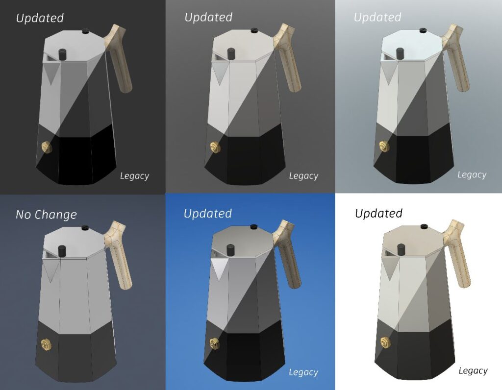
Visual Upgrade for Modeling Canvas
We’ve adjusted the tone mapping of the modeling canvas to enhance your visual experience. Now, you’ll notice improved edge visibility and increased brightness of materials in all environments. This means clearer and more vibrant models.
Data Management
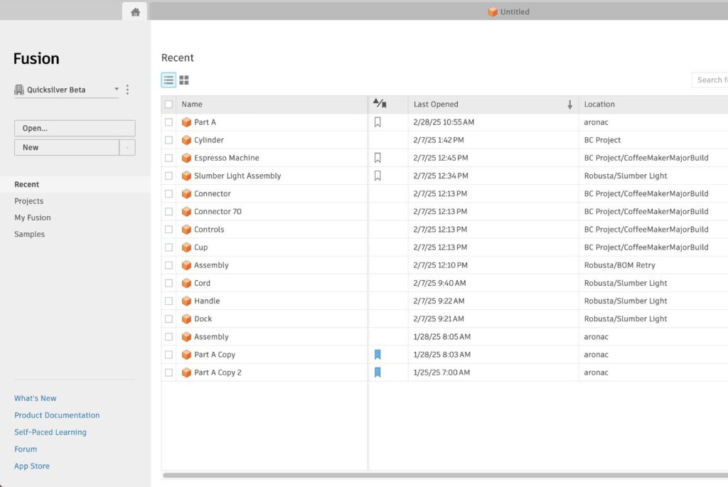
Improved Home Tab
The Home Tab now shows more data at once, helping you quickly access your project data and Recents list. This density aligns with the rest of Fusion desktop so that you don’t have to adjust to different information densities in the same application.
Collaborative Editing Enhancements
Collaborative editing is a broad term that signifies significant improvements Autodesk is making to Fusion data management. These changes will make it easier for you to collaborate with teammates, see concurrent changes in real-time, manage versions and part numbers, and more. We are progressively rolling this functionality out to everyone, so if you do not have it yet no need to worry.
Learn about Collaborative Editing Enhancements.
File->Save As experience enhancements (Collaborative Editing)
Save As functionality, which is used for creating another instance of a model file, just got better. Now the new Save As dialog box lets you choose between a new part number and a shared part number of the original design. If you choose to generate a new part number, root design will be separated and detached from the original part number and it’s Shared Part Number group. With this option, the properties of the root design also get copied.
Learn about Shared Part Numbers
Configure Internal Component Properties in Collaborative Editing Hubs (Collaborative Editing)
In this update, we’re enabling a workflow to let you configure properties for internal components in a Configured Design in Collaborative Editing hubs, matching the experience available in Commercial hubs.
In the Configuration Table, click the Properties tab to:
- View and edit properties for each configuration.
- Use the Add Components button to enter Configuration Mode, click internal components in the Browser to add them to the Properties tab, and configure their property values.
- View and edit properties of configured internal components.
Configuring properties allows you to have greater control over your configuration data while improving your management of components in downstream workflows.
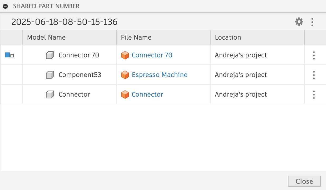
Show All Models in a Shared Part Number Group (Collaborative Editing)
If you are using the capability to group models via part numbers in a Shared Part Number group, Fusion desktop has a new feature to enhance your experience.
You can now easily open the list dialog box through the three-dot menu in the property panel header to view all the models that belong to your shared part number group.
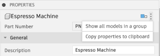
Additionally, you can conveniently navigate to the design in Fusion Desktop and Fusion Web from the model’s list by simply clicking on the file name.
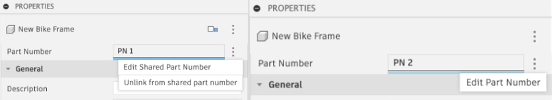
Part Number Editing (Collaborative Editing)
With this update, Part Number can now be edited via the following options:
- Edit Part Number – Available when the assigned part number is not a Shared Part Number
- Edit Shared Part Number – Renumbers the Shared Part Number for all the models in the group.
- Unlink from Shared Part Number – Edits the Shared Part Number only for the model and unlinks it from the group.
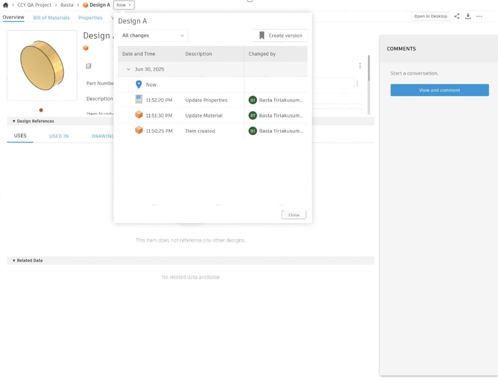
New History Panel Experience in Fusion web client (Collaborative Editing)
We are excited to bring the new history panel experience in Fusion web client to Collaborative Editing (CE) hubs. You can now enjoy the same history experience that is in Fusion Desktop, all within Fusion web client:
- View the list of historical changes made to your design
- Navigate between these changes
- Edit description of these changes (except system-generated ones such as description of a revision).
Enhanced History Panel Descriptions (Collaborative Editing)
For those using Collaborative Editing (CE) hubs, you can now edit the descriptions of changes displayed on the History Panel (both in desktop and web client). This allows you to describe your changes in a meaningful way, greatly facilitating collaborative workflows in Fusion.
Note: System-generated descriptions (such as revision descriptions) are not user-editable.
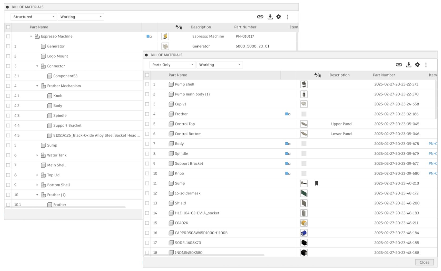
BOM Enhancements (Collaborative Editing)
We improved the auto refresh behavior in BOM as structure changes happen in subcomponents.
Additionally, we have added new BOM layouts options. You can now switch between:
- Structured layout – showing full assembly – child relationship structure (was already part of BOM)
- Parts Only layout – a new view showing a flat list of Components only, with their quantity aggregated across the structure. BOM Export will support this new Layout as usual.
Design
Assembly Just Got Faster: Introducing Constraints in Fusion
Say hello to a brand-new way to build assemblies in Fusion, faster, more intuitively, and with far greater flexibility.
With the new Constraints feature, you can define how components relate to each other using familiar constraint methods, ideal for complex assemblies across industries like consumer products, machinery, and more.
Unlike joints, which create a one-to-one relationship, constraints let you define multiple connections in a single command. For example, you can now use one constraint to connect a bracket simultaneously to a frame and a panel dramatically simplifying your workflow. Having all these relationships in one command makes your assembly neater and easier to make changes if needed. For those of you transitioning from Inventor or other CAD tools, these workflows will feel familiar and intuitive, easing the learning curve and accelerating productivity.
And this is just the beginning. Fusion’s constraint system will continue to evolve, unlocking even more powerful capabilities in future updates. Stay tuned!
Note: To declutter the workspace, we’ve unpinned joints from the toolbar, but they’re still just a click away in the dropdown in search or with the “J” shortcut. You can repin them anytime.
Learn how to Supercharge Your Autodesk Fusion Assemblies With Constraints.
Enhanced Offset Capability
We are excited to announce improvements to the offset feature based on your feedback: You can now create offset curves from any existing offset curve, even when ‘Match Topology’ is turned off.
Additionally, have improved the user interface to align with other features like ‘Extrude,’ making it easier and more intuitive for you to use.
Mesh Texture Extrude
We have an exciting mesh modeling update: Mesh texture extrude! With this feature, an image can be used to generate a textured surface on a mesh body. You can customize your texture extrusion by choosing the extrusion type, clearance from edges, blend distances and more in this new dialog. You can preview the outcome and easily generate the textured mesh model you desire.
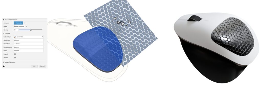
This new command can be found under the “Modify” panel of the “Mesh” tab in the Design Workspace.
Please note that the texture extrude command is a direct modeling function and is available when you are in ‘Direct Mesh Editing’ in “Parametric Modeling” mode or when you are in “Direct Modeling” mode.
Learn more about Mesh Texture Extrude.
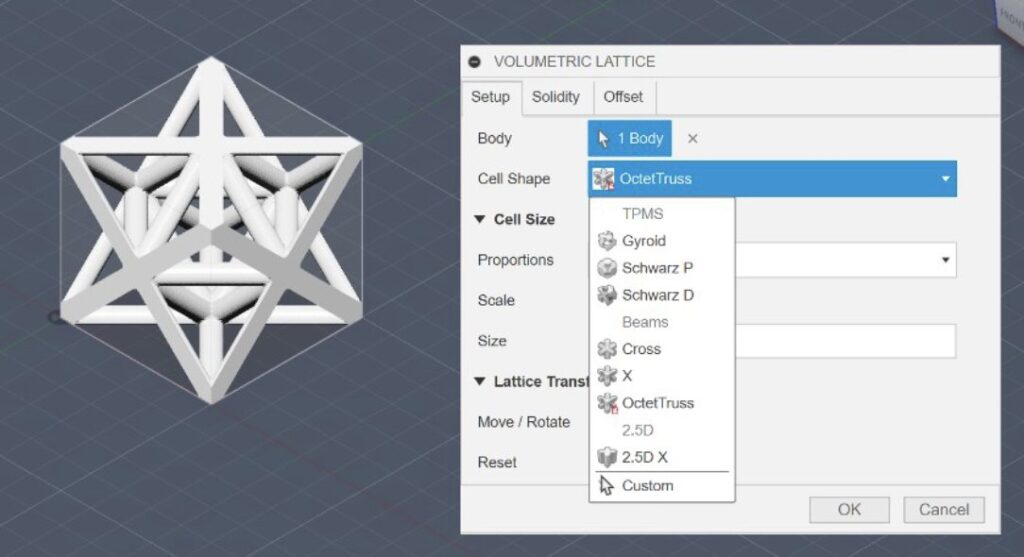
New Cell Types in Volumetric Lattice Command
When generating a volumetric lattice, if you select a “beam” cell shape (Example: Cross or X) Fusion now creates signed distance fields using a beam network, instead of formula-based representation to create the implicit model. This change will enable us to offer more beam style cell types in the future.
The newly introduced beam network representation is also offered in the Fusion API, giving you the freedom to create any beam-based Lattice as an implicit model. Our first new cell is the Octet Truss, with more planned in the future.
AutoConstrain Enhancements
AutoConstrain is now more powerful and easier to use than ever before. For those who frequently create turned parts or perform revolves, we have introduced Diametric dimensions. This new feature automatically recognizes your center lines and provides the diameter dimensions you’ve been asking for.
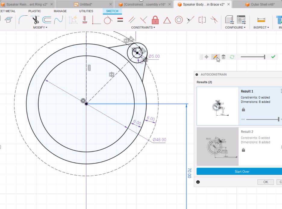
When using AutoConstrain, sketch dimensions are now editable with the AutoConstrain dialog open, simply double-click one and make a change. But that’s not all, our new a Heads-up Display now puts tools like Set Datum, Edit Dimension, Delete Dimension, Refresh & the Slider right where you need them.
Configure On The Fly Command Expansion
In the November 2024 release of Fusion, we added a Configure tab to some of the most-used modeling commands, to make it easier to configure aspects as you model without interrupting your design flow.
As we did in the January, March, and May releases, here in July we continue to expand the list of commands supported in this workflow to include more Assembly tools.
As you create or edit a configurable feature:
- Use the controls on the Feature tab as normal to define the feature
- Switch to the new Configure tab
- Check the aspects you want to configure
- Click OK to complete the command
Each aspect you checked is added as a column in the Configuration Table, and you can continue modeling without the need to switch contexts. You can find the new contextual Configure tab in the Joint command dialog under Assemble.
Stay tuned as we support additional commands in future releases.
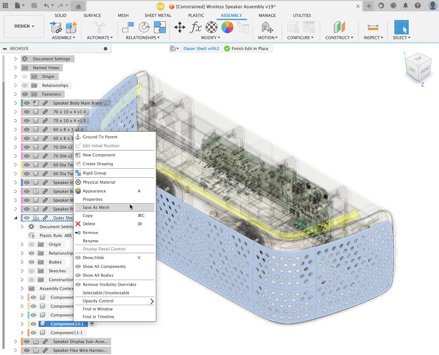
Expanded Edit in Place Support Coverage
We are pleased to announce that the ‘Edit in Place’ feature is now supported for the following commands: History, Find in Timeline, and Save as Mesh.
Drawings
New Custom Sketch Symbols
Introducing Sketch Symbol feature in drawings! Now unlock symbol customization by designing your own symbols or importing them from existing drawings. Sketch Symbols can be attached with leaders and equipped with automatic Alpha or numeric counters. This is ideal for Flag notes, Inspection bubbles, custom balloons, or ISO/DIN 5459 Style Datum Target Symbols.
Learn more about Sketch Symbols.
Auto Scale and Tidy up improvement
We’ve made improvements to our auto scale algorithm, increasing the quality of all automatic drawing results by scaling the size of the view intelligently. This improvement will also affect tools like Tidy Up, which make use of this algorithm as well.
Electronics
Dark Mode for Electronics Workspace (Preview)
Earlier this year we announced the addition of the UI Themes preview to Fusion, allowing you to enable Dark Mode. With each update, we have been working on improving the preview to cover more and more features and functionality. As of this July you can enable Dark Mode for the Electronics Workspace. To do this first activate UI Themes from the Preview Features in the Preferences dialog. Then, you can select your preferred theme: Dark Blue, Light Gray, or Fusion Classic.
Simulation
Fluid Path Study Preview in Generative Design will be retiring soon
The Fluid Path Study, currently available as a preview feature in the Generative Design workspace, will be retired at end of August 2025. This is the first step towards retirement of the Fluid Path Study and will have the following effects:
- You will not be able to create new or clone a Fluid Path Study.
- You will no longer be able to generate outcomes for a Fluid Path Study that you may have created in the past.
- If you have generated outcomes for a Fluid Path Study, you will continue to have access to those outcomes and you will also be able to export an outcome.
We sincerely thank you for using this preview capability and providing your feedback.
Manufacturing
Thread Parameters Moved to the Geometry tab
We are pleased to inform you of an important update to the Thread strategy parameters, aimed at enhancing the logical flow and efficiency of your workflow.
In our quest to continuously improve your experience, we have relocated key thread parameters to the Geometry tab. Now, these parameters are conveniently organized within a new Thread group:
- Threading Hand
- Thread Pitch
- Pitch Diameter Offset
For the Turn Thread strategy, the following parameters have been moved from the Passes tab to the Geometry tab, also within the Thread group:
- Threading Hand
- Thread Pitch
- Thread Depth
These parameters represent the thread geometry, so they fit better on the Geometry tab. This change is the first step toward future improvements in these strategies.
Learn more about how to Generate a Turning Thread toolpath.
Canned Cycle output for Undercut Profile Roughing
In CNC Turning, the use of “Canned cycles” have been around for almost as long as G-Code itself has existed (b. 1958). In many cases, Canned cycles permit complex toolpaths to be implemented with very few lines of g-code. The benefit to the user is that the code is compact, easy to read and edit as well as not taking up a lot of storage space.
We now allow for canned cycle output for turning profile roughing operations when machine undercuts is checked. Like other toolpaths and Canned Cycles, we do not allow “Rest Machining” to be enabled, as well as in the case of Undercuts, one must enable “Allow Radial or Axial Grooving” (which is going to be dependent on direction of travel).
Learn how to Generate a Turning Profile Roughing toolpath.
Enhanced Point Selection for Multi-Axis Parameters and Spherical Clearance Areas
Following your suggestions, you can now apply offsets in X, Y, and Z when using the To/From Point options to specify the Primary Tool Axis or the Avoidance Mode for Collision Avoidance. These new options eliminate the need to return to the Design workspace to create a new point for position adjustments, streamlining your process.
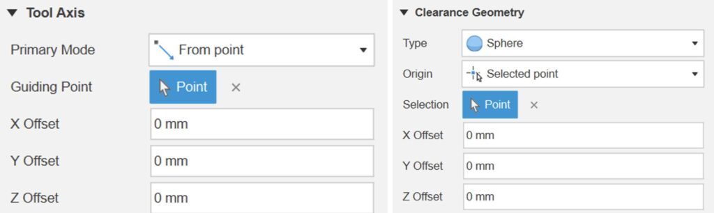
Similarly, when defining the center of a spherical clearance area from a selected point, you can apply offsets in X, Y, and Z. This allows for more convenient and precise positioning. We’re continually improving based on your requests. If you’d like to see these options implemented in other areas, please let us know!
New Ability to Restart In-Process Stock Generation
In-Process Stock (IPS) manages the current state of the stock for each successive toolpath, but sometimes the IPS fails to generate or the calculation does not complete. This can happen in a range of circumstances, for example if you duplicate a toolpath or change the order of the operations. If the IPS calculation is incomplete, the toolpath simulation is likely to be inaccurate.
If the IPS calculation failed to complete, there has been no quick or easy way to restart the IPS calculation. You would have to workaround the problem by regenerating toolpaths or by closing and reopening Fusion.
We provided the ability to restart the IPS generation calculation, making it easier and faster to recover from situations where the In-Process Stock generation has failed to complete.
Improved Performance for Large Selection Workflows
We have improved the performance in the manufacturing workspace when you select large numbers of faces, whether selecting faces individually or working with selection sets. If you already have a selection with a large number of faces and click on additional faces to extend the selection, the performance will deteriorate less quickly as the selection increases- you will continue to experience good performance for greater number of selected faces. You will see greater performance improvements with larger numbers of selected faces.
Saving and Recalling Toolpaths for Configured Design on a Per-Configuration Basis
In this release, we’ve significantly improved productivity for manufacturing users working with Configured Designs. Previously, activating one configuration would invalidate all setups and operations for other configurations, necessitating the regeneration of toolpaths even when revisiting a previously calculated configuration. Now, with enhanced functionality, toolpaths are saved on a per-Configuration basis. This means you can recall previously calculated toolpaths when you revisit a Configuration, eliminating the need for recalculation and easing frustrations. A Configured Design contains two or more Configurations defined in a Configuration Table, and this update allows streamlined toolpath management across all your configurations.
Learn more about Manufacture Configurations.
All Finishing Cutting Passes in 2D Contour Now Use Finishing Feedrate
We’ve enhanced the 2D Contour feature in Fusion to provide a more consistent experience for finishing cutting passes. Previously, only the last finishing pass used the specified feedrate set by the user. With this update, all finishing cutting passes will now use the specified feedrate, ensuring uniformity throughout the process.
How to Use:
- Enable Multiple Finishing Passes: In your settings enable the option for multiple finishing passes.
- Specify Number of Finishing Passes: Set the number of finishing passes to be greater than 1.
- Run Simulation: Execute a simulation of the cutting paths.
- Check Feedrate: Verify that the feedrate for all finishing cutting paths is consistent and matches the value specified in the GUI.
With this improvement, you can expect a more predictable and controlled finish on your components, enhancing the overall quality of your manufacturing process.
Learn more about 2D Contour.
Auto-Generated Drive Curves in Blend
Define Blend toolpaths more easily with the latest update. Rather than defining the drive curves explicitly, simply select the region to be machined and opt for the passes to be calculated from the surface boundary. The sections of the region’s perimeter to blend between will be determined automatically. As before, for complete control, there is the option to specify the curves explicitly.
Learn more about Blend.
Additive Manufacturing
New Part Placement Functionality for Additive Arrange
This release we have some big updates for Additive Arrange. Firstly, we have added a new “Placement” option to the 2D Arrange (True Shape), 3D Arrange (True Shape) and 3D Arrange (Bounding Box) arrangement types. This allows you to have more control over how your components are placed in the build volume of your 3D printer.
If you select ‘Center’, the first arranged component will be placed in the center of the build platform. The arrangement type you selected will prioritize placing the subsequent parts around the initial part in a circular fashion.
If you select ‘Lower Left Corner’, your first arranged component will be placed close to the bottom left corner of the build volume. The subsequent parts will be placed along the X axis first, Y axis next and finally the Z axis of your available build volume.
Learn more about Additive Arrange.
Components’ Custom Rotation Settings Now Displayed
We updated the “Additive Arrange” dialog to display the custom rotation input per component below the component table. This makes it much easier to see what custom rotations have been set for each component.
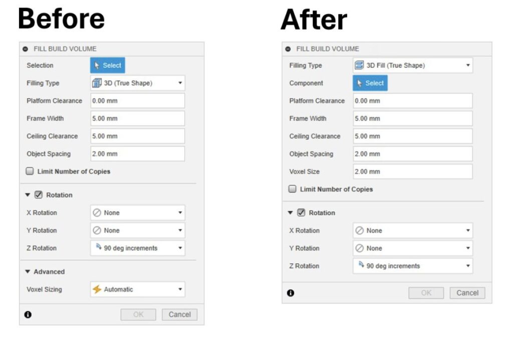
Improved Consistency Between Additive Arrange and Fill Build Volume Dialogs
We also updated the name of certain parameters, and the user interface options of the Additive Arrange and Fill Build Volume dialogs. These changes were made to improve the consistency between the two dialogs. The most notable update impacts the “Voxel Sizing” setting within the “Fill Build Volume” dialog. This setting is no longer a drop-down menu within the “Advanced” section of the dialog. It is now a numerical input field and is relocated within the dialog to be below the “Object Spacing” input field. The default value for “Voxel size” is set to 2 mm, as this value offers a good balance between calculation performance and object spacing result accuracy.
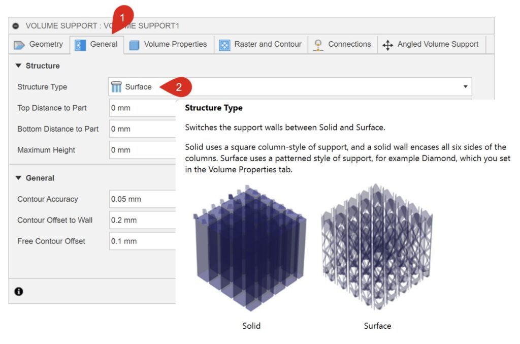
Improved User Interface for Volume and Polyline Support Dialogs
Continuing with the user interface updates, we have renamed and repositioned some of the support structure settings. These changes can be seen in Metal Powder Bed Fusion additive setups, when using Volume or Polyline supports. The main change is to the “Structure Type” for the Volume supports, and the “Polyline Type” for the Polyline supports. Both now use “Surface” and “Solid” instead of “Structured” and “Closed Volume”. The icons have also been updated.
Learn more about Volume supports.
Learn more about Polyline supports.
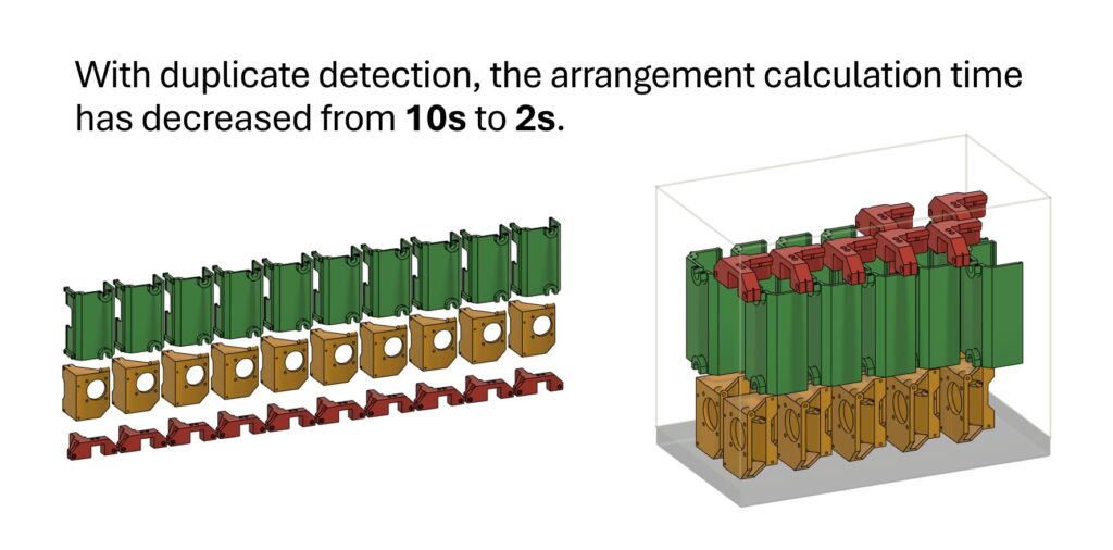
Performance Improvements for True Shape Additive Arrangement
We also significantly increased the performance of the True Shape arrangement type for certain workflows. True Shape arrangement type can now detect duplicates of a given component ahead of performing the part arrangement calculations. This means that True Shape algorithm can arrange parts quickly and efficiently regardless of whether you create your duplicates before packing your parts or during the packing operation.
Inspection
New Import All Results for Inspection Results (Manufacturing Extension)
We made a big improvement to Import Inspection Results, now you can import multiple sets of inspection results data without resorting to manual file edits or external automation scripts.
Learn how to import the results from an inspection.
Manufacturing Sustainability Insights (MSI)
Manufacturing Sustainability Insights (MSI) is a new tool designed to help Fusion users build greener products.
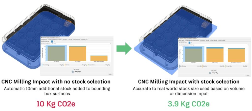
Stock Material Overrides
We’ve heard your feedback about the default assumptions for stock material dimensions not always matching real-world practices. Previously, MSI added a standard buffer around the part geometry, which wasn’t always accurate. Now, you can define your own stock dimensions for CNC machining, CNC turning, and even metal additive manufacturing. This means more precise material usage calculations and less waste!
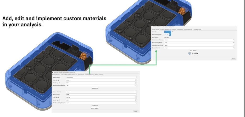
Custom Materials Library
You also told us you need more flexibility with materials, especially when working with new or sustainable options. Now, you can add custom materials to the library, specifying their carbon impact and density. This ensures that your sustainability assessments reflect the unique materials you’re using.
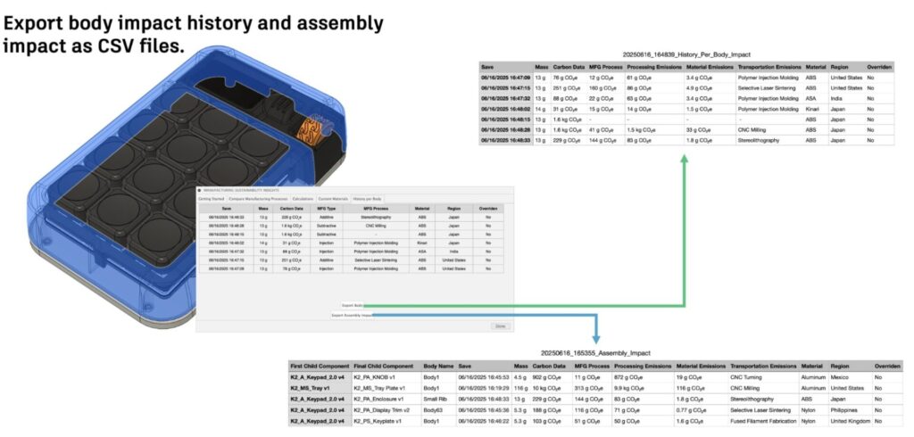
Enhanced Export Options
Another common request was for better data export capabilities. We listened and now offer more granular export options. You can export a detailed history of changes for a single part or export the entire assembly’s analysis data as a CSV file. This makes it much easier to integrate MSI data into your workflow and share insights across your team.
Post Processor and Machine Simulation
Looking for the latest post processors and machines updates? This July we released a ton of new updates and improvements to many of the open-source Post Processors and Machines we offer for free. Within this release you will find improvements to post processors including Generic Post Processors, Milling Post Processors, and Turning Post Processors. We also added new machines to our Machine Library, updated our Workholding library, and improved functionality around the Autodesk CAM Post Processor engine.
Learn what’s new for Post Processors and Machine Simulation this July.
Missed the June update? Learn what’s new for Post Processors and Machine Simulation from this past June.
Insider Program
Do you want to engage more with the Autodesk community? Check out the Fusion Insider program to use exclusive previews, and test out the latest build before it’s released to the public?
As a member, you’ll gain inside knowledge of updates and a first look at new features. You’ll also be able to join exclusive events and try pre-release functionality. Plus, you can give feedback directly to the product teams.
Release Notes
But wait, that’s not all! To see more fixes, minor enhancements, and keep up with the latest check out our Release Notes for the full rundown on changes to Fusion and Fusion web client.