Gears are fundamental components in mechanical designs, serving to transmit power and motion between various parts. Autodesk Fusion offers multiple methods for creating and inserting gears into your assemblies or designs. This article will walk you through the process of creating and inserting gears in Fusion and discuss the two primary approaches: creating custom gears using the Spur Gear add-in and inserting standard gears from manufacturers.
Custom gears in Fusion with the spur gear add-in
One effective way to create gears in Fusion is by utilizing the Spur Gear add-in. This tool allows users to design a custom gear tailored to specific requirements. The add-in provides the ability to customize parameters such as module, pressure angle, and root fillet radius. Acting as a gear generator, the Spur Gear add-in streamlines the process of creating gears in Fusion. Creating gears with this add-in often involves using a circular pattern to efficiently replicate gear teeth around the central axis. The gear model is created and added to your project. Here’s how to access and use the add-in:
Step 1: Access the spur gear add-in
- Navigate to the Utilities Tab: Open your design workspace and find the Utilities tab located at the top of the screen.
- Select Scripts and Add-ins: From the Utilities tab, click on the “Scripts and Add-ins” option.
- Run the Spur Gear Add-in: Scroll to the bottom of the list and find the Spur Gear option. You can identify it by its blue icon. Click on it and then press the “Run” button. This action will activate the Spur Gear add-in and open its dialog box.
Step 2: Customize your gear
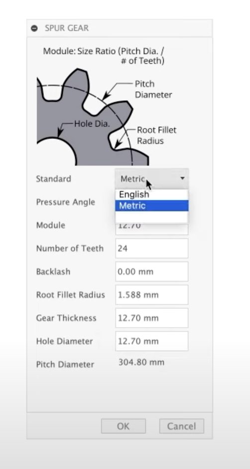
In the Spur Gear dialog, you’ll find a helpful diagram illustrating gear components, which is beneficial if you’re new to gear design. It’s important to enter precise gear details such as teeth count, module, pressure angle, and root fillet radius, as these details directly affect the gear’s dimensions, strength, and functionality.
The dialog box allows you to adjust several parameters for your gear:
- Dimensions: Choose between imperial and metric units based on your project needs.
- Settings: Modify the number of teeth, pitch diameter, and other specifications to create a gear that meets your design criteria. The relationship between pitch diameter and number of teeth can be defined by an equation, which helps ensure correct gear ratios. The add-in provides default values for many settings, but you can adjust these as needed for your application.
Step 3: Finalize the gear design
Once you’ve set all the desired parameters, click “OK” to generate the gear. The add-in will model the gear and add it as a component in your project’s browser. You can also review the timeline to see the modeling steps taken to create the gear. If needed, you can edit these steps or model the gear manually based on your preferences.
Understanding gear parameters and dimensions
Pitch diameter
One of the most crucial parameters to consider is the pitch diameter. This is the diameter at which the gear teeth effectively engage with those of a mating gear.
In the Spur Gear add-in, the pitch diameter is displayed as a read-only value and is shown in the gear diagram, making it easy to reference while creating or adjusting your gear. It’s important to remember that the pitch diameter is different from the outside diameter—the pitch diameter is crucial for spacing and meshing, whereas the outside diameter represents the total diameter of the gear. Understanding this distinction is key to avoiding interference and ensuring proper meshing of your spur gears.
Gear thickness
Another important setting is the gear thickness, which indicates the extruded height of your gear in Fusion. After generating your gear with the add-in, you can adjust the thickness by selecting the top face, right-clicking, and using the “press pull” feature to set your desired dimension. This flexibility allows you to customize the gear to fit your assembly’s requirements.
Gear tool profile
The gear tooth profile is also customizable within the Spur Gear add-in, enabling you to create gears with the precise number of teeth and tooth shapes required for your project. The module (for metric gears) and diametral pitch (for English gears) are critical parameters that define the size and spacing of the gear teeth. The module is calculated as the pitch diameter divided by the number of teeth, while the diametral pitch is the number of teeth divided by the pitch diameter. These settings ensure compatibility with other components and adherence to your design specifications.
Backlash
Backlash is another essential factor to consider. This refers to the clearance between the teeth of mating gears, which prevents binding, reduces the risk of overheating, and allows for proper lubrication. For 3D printed gears, a common backlash setting is around 0.15mm per gear (totaling 0.3mm), though you may need to adjust this value based on your specific printer and material. Proper backlash ensures smooth operation and extends the lifespan of your gears.
Root fillet radius
Lastly, don’t overlook the root fillet radius, which is the curved transition between the gear tooth surface and the root. Setting this radius too large can trigger a warning in Fusion 360 and may cause undercutting, which weakens the gear and disrupts proper meshing. Always verify the maximum allowable root fillet radius in the add-in to ensure gear strength and functionality.
Generate the gear
Once you’’ve set all the desired parameters, click “OK” to generate the gear. The add-in will model the gear and add the gear will be added as a new component in your project’’s browser. For better project management, it’s recommended to organize gears as top level components to keep your assembly structured and easy to navigate. You can also review the timeline to see the modeling steps taken to create the gear. If needed, you can edit these steps or model the gear manually based on your preferences.
If you need to edit or position the gear, select the correct axis to rotate and align the gear precisely within the assembly. Use the rotate function to set the gear’s orientation for proper meshing, and you can drag the gear to adjust its position. When placing multiple gears, ensure the correct distance between them by summing their pitch radii or diameters for proper engagement. If your design requires support, add a rest or riser beneath the gear. To guide gear alignment and motion, consider creating a track or path in your assembly.
Before finalizing the design, test the gear’s operation using the simulation tools in Fusion to verify smooth movement and engagement. Ensuring proper gear operation is critical for durability and performance.
Inserting standard gears from manufacturers
If you prefer using a standard, off-the-shelf gear, Autodesk Fusion provides options to insert pre-made gear models directly into your designs. These gear files can often be downloaded from the manufacturer’s website or specific catalog page, ensuring you have the correct specifications for your project.
Here’s how to do it:
Step 1: Open the insert menu
- Navigate to the Insert Menu: At the top of the Fusion workspace, locate the Insert menu. This menu offers several options for adding components.
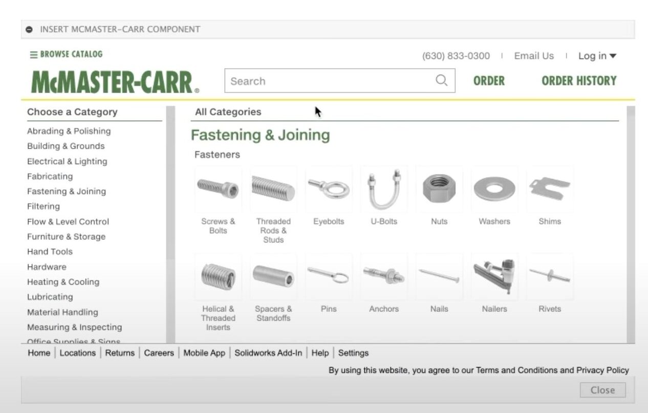
- Select Manufacturer Parts: Within the Insert menu, choose the option for inserting parts from manufacturers. This feature allows you to access parts catalogs from various suppliers, such as CAD libraries and McMaster-Carr. When selecting a gear, consider the matter (material) of the gear, as it affects performance and durability. For detailed gear specifications and assembly relationships, refer to the relevant figure in the manufacturer’s documentation.
Step 2: Search for gears
Once you’re in the manufacturer parts section:
- Filter Your Search: Enter specific criteria like gear type, diameter, or number of teeth to find suitable gear models.
- Select a Gear: Browse through the options and click on the product detail of a gear that fits your requirements. Make sure to set the drop-down menu to STEP format for compatibility.
Step 3: Download and insert the gears in Fusion
Press the download button to insert the gear as a component in your design. It’s important to note that this gear will be in a STEP file format, meaning you won’t be able to edit its internal Fusion parameters like you can with custom gears. However, you can still use direct modeling techniques to make adjustments. For example, you can create sketches or features on the gear surface, and use the offset feature to create a gap between the gear and the base plate or to adjust the fit of gear pins.
Thankfully, even after inserting the gear, you can easily modify its thickness or other dimensions using these modeling tools. If you need to ensure proper alignment or meshing, you can refer back to past measurements or parameters from earlier steps in your design process.
Whether you choose to create a custom gear using the Spur Gear add-in or insert a standard gear from a manufacturer, both methods are valuable for incorporating gears into your Autodesk Fusion projects. Understanding these processes allows for greater flexibility in your designs, enabling you to select or customize gears according to your project’s specific requirements. By mastering these techniques, you can enhance your mechanical designs and ensure they operate effectively within your assemblies.
And there you have it! You’re now ready to insert gears in Fusion. Give it a try today.