 Jim Byrne
Learn how to run thermal stress simulations in Autodesk Fusion to predict thermal expansion, validate designs, and improve product reliability.

Elevate your design and manufacturing processes with Autodesk Fusion
Thermal stress analysis is an essential tool for engineers who need to understand how temperature changes affect their designs. When components heat up or cool down, they expand or contract at different rates depending on their material properties. This can lead to warping, deformation, or even failure if not properly accounted for during the design phase.
In Autodesk Fusion, thermal stress simulations allow you to evaluate stresses induced by thermal loads while simultaneously applying mechanical loads like gravity, pressure, or force. The results show the combined effect of both structural and temperature-induced stresses, giving you a complete picture of how your design will perform in real-world conditions.
Understanding thermal stress analysis
Thermal stress studies evaluate how parts respond when subjected to temperature changes. A component may warp as temperatures fluctuate, and different materials expand at different rates. This type of analysis is particularly valuable when you need to:
- Predict thermal expansion and contraction
- Evaluate combined thermal and mechanical loading
- Optimize material selection for thermal applications
- Verify that assemblies maintain proper function across temperature ranges
Real-world application: Simulating a circuit breaker
To demonstrate the power of thermal stress analysis, let’s walk through simulating a thermal circuit breaker. This device disconnects an electrical circuit when it gets too hot due to current overload.
Inside a circuit breaker, a bimetallic strip made of two materials with different coefficients of thermal expansion expands at different rates as temperature increases. This causes the strip to bend, eventually moving away from the contact point and opening the circuit.
Our simplified circuit breaker model includes:
- A bimetallic strip (the core thermal element)
- A contact plate that completes the circuit
- A spring that holds the contacts in place under normal operating conditions
The simulation goals are straightforward: verify that the breaker expands enough to disconnect under overload conditions, and ensure the contacts remain closed during normal operation.
Setting up your thermal stress study
Switching to the simulation workspace
Start by navigating from the Design workspace to the Simulation workspace. Click on the workspace selector and choose Simulation. Fusion will prompt you to select a study type. Choose Thermal Stress and click Create Study.
Simplifying the model
Model simplification is a critical step that balances accuracy with computational efficiency. You need to consider which components significantly affect the results and which have minimal impact.
Click Simplify in the ribbon. This tool removes components from the simulation workspace without affecting your main design. For the circuit breaker example, removing the spring speeds up the simulation significantly. In reality, the spring has minimal effect on overall thermal expansion.
To remove a component, select it from the model, right-click, and choose Remove. When finished, click Finish Simplify. Remember that removed components still exist in your Design workspace.
Assigning materials
Material properties drive thermal expansion behavior. The bimetallic strip requires two different materials to function properly.
Click Study Materials in the toolbar. By default, components use their design workspace materials. For the bimetallic strip, change the inner part from steel to brass by selecting it and choosing brass from the Fusion library dropdown.
Brass and steel work exceptionally well as bimetallic materials due to their different thermal expansion coefficients. You can verify material properties by clicking Properties and reviewing the thermal expansion coefficient. The outer strip remains steel.
Applying structural constraints
Constraints define how your model is fixed in space. For the circuit breaker, apply fixed constraints to simulate bolted or riveted connections.
Select Structural Constraint from the constraints dropdown. Choose Fixed as the constraint type. Select the two holes at the bottom of the base plate as targets. Repeat this process for the contact strip holes.
This simulates the component being rigidly attached at these points. More advanced constraint types exist for different scenarios, but fixed constraints are sufficient for this model.
Applying thermal loads
Thermal stress studies require both thermal and structural loads. Start with thermal loads.
Convection load
Convection represents heat removal by air cooling. Without it, the part would heat up indefinitely, which isn’t realistic.
Change the load type to Convection and select all external faces except where the bimetallic strip parts touch each other. The convection coefficient depends on several factors:
- Surface geometry
- Material roughness
- Forced convection (fans or airflow)
Typical convection coefficient values:
| Cooling Type | Coefficient (W/m²·K) |
|---|---|
| Natural air cooling | 5-10 |
| Light airflow | 10-25 |
| Forced air cooling | 25-100 |
| Liquid cooling | 500+ |
For a circuit breaker inside an enclosure with no forced cooling, use 5 W/m²·K.
Ambient temperature
Specify the ambient temperature surrounding the breaker. This is critical because thermal expansion depends on temperature difference, not absolute temperature.
Choose an ambient temperature appropriate for your application:
- Consumer electronics: 25-30°C
- Industrial enclosure: 40°C
- Automotive environment: 60°C
For this example, use 30°C to represent the temperature inside an electrical enclosure.
Internal heat load
Internal heat represents electrical heating from current flowing through the breaker. Click Load, select Thermal Load, change the load type to Internal Heat, and select all three bodies.
This heat comes from resistive losses calculated using the formula: Power = I²R, where current flowing through the material generates heat.
Apply 2 watts to represent normal operation. This value should come from electrical calculations, measured test data, or power dissipation specifications. Using internal heat instead of applied temperature produces a more realistic simulation because the breaker heats up due to electrical current, not environmental temperature.
Applying structural loads
The spring force keeps contacts closed during normal operation. Click Load and select Structural Load. Apply 1.5 Newtons to the contact plate face to represent the spring force acting downward.
The closer your simulation matches reality, the more representative your results will be. Include all significant forces in your model.
Configuring contact settings
Contact settings determine how heat and forces transfer between components. Click Automatic Contacts and generate contacts. This creates bonded contacts across all touching surfaces.
However, you need to modify the contact between the breaker point and the plate. Click Manage Contacts and locate the contact where the point touches the plate. Change this contact type from Bonded to Separation. This allows the parts to separate during the simulation, enabling the circuit breaker to operate.
Also change any small fillets in this area to Separation.
Refining the mesh
Mesh quality directly affects result accuracy. Click Mesh to generate the initial mesh. To refine the mesh around curved surfaces, click the pencil icon for advanced settings and enable Create Curved Mesh Elements.
This option is only available with parabolic elements. It allows Fusion to generate a more complex mesh that follows curved surfaces accurately. This is essential for correct calculations at the node point where the contact plate meets the curved surface.
Curved mesh elements conform more accurately along curved geometry and enhance simulation accuracy. After editing settings, regenerate the mesh to see the improved representation around curved surfaces.
Running the simulation
Click Solve in the toolbar. Verify that the extension is active and solve the study. You can monitor progress through the job status bar.
One of the great advantages of cloud simulation is that you don’t need to wait for each study to complete before setting up the next one. You can run multiple scenarios simultaneously.
Creating comparison studies
To evaluate the overload scenario, right-click on your study and select Clone Study. Edit the internal heat load from 2 watts to 5 watts to simulate circuit overload. Click Solve on this study as well.
You can continue duplicating studies to compare different scenarios, such as different spring values or material combinations.
When a study completes, you’ll receive a notification and the blue circle indicator will change to a green checkmark.
Analyzing results
Viewing displacement
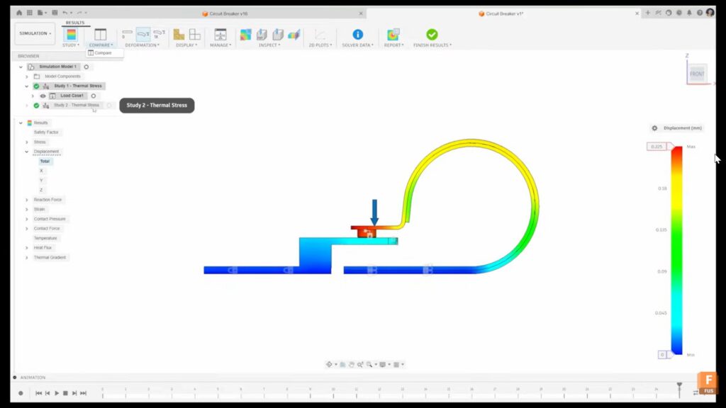
Click into your results. The default view shows safety factor, but displacement is the critical metric for this analysis. Change the result type to Displacement and select Total.
Initially, the deformation scale is set to an adjusted scale, which can exaggerate results. Change this to Actual to see true displacement values.
For the normal operating current study, displacement is very small with the contact point barely touching. This confirms the breaker remains closed during normal operation.
Comparing studies
Use the Compare option to view multiple studies side by side. Click Compare and select which studies to display. You can synchronize scales across studies for accurate comparison.
Without synchronized scales, each study shows its own minimum and maximum values, which can be misleading when comparing results.
For the overload current study, displacement is much larger, clearly breaking the circuit. This confirms the breaker operates as intended.
Using inspection tools
Inspection tools provide detailed result analysis:
- Minimum/Maximum Probes: Automatically identify and display extreme values
- Point Probes: Query results at specific locations
- Surface Probes: Trace results across surfaces
- Cutting Planes: Section the model to view internal results
For example, cutting through the center plane reveals internal stress and temperature distributions.
Animating results
Use the animation controls at the bottom of the screen to visualize how displacement evolves over time. This helps you understand the sequence of events during thermal expansion.
Generating reports
Share your findings with colleagues by generating a report. Click Report Settings and select Web View. Click Preview to see a comprehensive document containing all study settings, loads, constraints, and results with multiple views.
This report format is ideal for design reviews and documentation.
Best practices for thermal stress analysis
- Balance model complexity with simulation time: Simplify models by removing components that don’t significantly affect results. Every additional component increases solve time, so focus on what matters.
- Use accurate material properties: Thermal expansion coefficients vary significantly between materials. Verify that your material library data matches your actual materials, especially for critical applications.
- Apply realistic boundary conditions: Convection coefficients and ambient temperatures dramatically affect results. Research appropriate values for your specific application rather than using generic defaults.
- Validate with test data: Whenever possible, compare simulation results with physical testing. This builds confidence in your model and helps you refine assumptions.
- Run multiple scenarios: Don’t rely on a single simulation. Evaluate best-case, worst-case, and typical operating conditions to understand the full range of behavior.
- Check mesh quality: Refine the mesh in areas of high stress gradients or complex geometry. Use curved mesh elements for accurate results along curved surfaces.
- Document your assumptions: Record all assumptions about loads, boundary conditions, and simplifications. This documentation is invaluable when reviewing results or updating the model later.
Conclusion
Thermal stress simulations in Autodesk Fusion combine temperature and structural physics to predict how components behave under real-world conditions. By following this systematic approach, you can confidently evaluate thermal expansion, verify design performance, and optimize material selection.
Thermal stress simulation frequently asked questions
Thermal stress analysis in Autodesk Fusion predicts how temperature changes affect a part or assembly by combining thermal loads with mechanical loads such as force, pressure, or gravity. Engineers use it to evaluate thermal expansion, deformation, and stress before manufacturing.
Thermal stress simulation is available in Autodesk Fusion’s Simulation workspace, helping teams validate designs earlier and reduce costly physical testing.
Use a thermal stress simulation whenever temperature changes may affect product performance. Common applications include electronics, circuit breakers, automotive components, industrial equipment, and assemblies made from multiple materials with different expansion rates.
Autodesk Fusion allows engineers to evaluate thermal and structural behavior in a single study, making it easier to identify potential reliability issues during design.
Thermal stress simulations help identify excessive stress, warping, deformation, and material expansion before a product is manufactured. Detecting these issues early can reduce design iterations, improve reliability, and lower development costs.
Run thermal stress studies in Fusion to test performance across operating conditions before investing in prototypes or production tooling.
Yes. Autodesk Fusion thermal stress studies combine temperature-driven effects with structural loads such as force, pressure, gravity, and constraints. This provides a more realistic representation of real-world operating conditions.
Using a single simulation environment helps teams understand how thermal and mechanical forces interact and impact overall product performance.
Autodesk Fusion provides results including displacement, stress, temperature distribution, safety factor, and deformation. Engineers can also compare multiple design scenarios, inspect critical locations, create animations, and generate detailed reports.
Compare design alternatives quickly with Fusion’s cloud-based simulation tools and make more informed engineering decisions before production.