Discover what’s new in the March Fusion update, from isoparametric curves and modernized simulation results to live BOM updates and expanded manufacturing workflows.
Table of Contents
- Autodesk Assistant (Tech Preview)
- Minor Updates
- Highlights
- Usability
- Data Management
- Design
- Drawings
- Electronics
- Simulation
- Manufacturing
- API
- Insider Program
- Release Notes
Autodesk Assistant (Tech Preview)
v.2701.1.27 – March 16, 2026 (Minor Update)
Autodesk Assistant is expanding its role within Fusion with a new Tech Preview that introduces a redesigned experience and new ways to interact with design, manufacturing, and project workflows.
Autodesk Assistant is not designed to replace engineering judgment. Instead, it helps streamline everyday workflows by reducing repetitive clicks, surfacing answers faster, and helping execute common tasks in Fusion while you stay in control of decisions and outcomes.
Enhanced Autodesk Assistant Experience
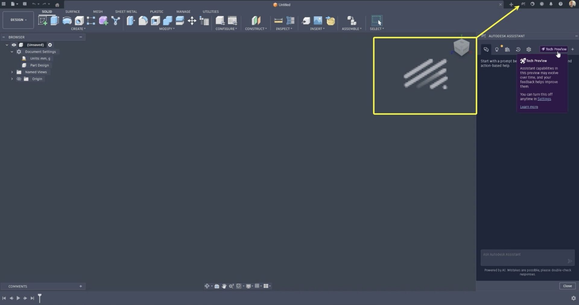
You’ll now find Autodesk Assistant through a dedicated button in the upper-right corner of both the Home tab and the main Fusion interface, making it consistently visible whenever you need support.
When opened, the Assistant appears in a docked panel along the right side of the Fusion window. The layout keeps important controls like the ViewCube, timeline, and toolbar unobstructed, allowing you to continue working while interacting with the Assistant.
The experience is also context aware. Whether you open Autodesk Assistant while setting up projects on the Home tab or while actively working in a design, the guidance adapts to where you are and what you are doing.
Conversational Design Assistance
One of the most powerful additions in this update is the ability to describe modeling tasks in natural language and have Autodesk Assistant map your request directly to the appropriate commands.
Instead of navigating menus or searching for the right command, you can simply describe what you want to do. Autodesk Assistant can help create basic geometry, apply common modeling features such as Extrude, Fillet, Chamfer, Hole, Shell, and Split, and update existing features by adjusting parameters.
It can also assist with a broader range of design tasks, including assigning materials and appearances, inspecting and interacting with the design timeline, creating sketches with dimensions, generating circular and rectangular patterns, and creating revolve features and additional primitives such as spheres, toruses, and coils.
You can also ask questions about your design, such as volume or surface area, identify specific geometry, highlight elements, or perform batch actions across larger models.
The goal is simple: reduce the friction between idea and execution so you can focus on design intent.
Manufacturing Assistance
Additionally, Autodesk Assistant now extends into the Manufacturing workspace, helping simplify CAM setup and toolpath workflows.
Using natural language, you can create manufacturing setups, generate toolpaths, rename or batch rename operations, select tools, and ask context-specific questions about manufacturing workflows without breaking your flow. The Assistant can also help clarify available options within the Manufacturing workspace, providing guidance as you configure setups and operations.
Project and Collaboration Assistance (Collaborative Editing)
And that’s not all. Autodesk Assistant can also help streamline the administrative work that surrounds design and manufacturing.
Using natural language, you can create projects, organize folders, invite team members, review permissions, and manage collaboration settings. Rather than navigating multiple admin panels, you can manage these tasks conversationally while the Assistant confirms changes before applying them.
Whether you’re setting up a new project, organizing manufacturing assets, or adjusting access across a growing team, Autodesk Assistant is here to help.
Looking Ahead
This is just the beginning. Autodesk Assistant will continue to expand as we develop new capabilities and refine how it supports design, manufacturing, and collaboration workflows inside Fusion.
Want to be the first to see what’s coming next and try new features before they go live? Check out the Fusion Insider Program for early access to upcoming innovations.
Minor Updates
Our latest minor update brings several important fixes and improvements to enhance your experience. Click to learn more.
v.2701.1.18 – March 4, 2026 (Minor Update)
Usability
- Resolved an issue where Autodesk Assistant would incorrectly open on launch.
Highlights
v.2701.1.15 – March 2, 2026 (Major Update)
Backwards Compatibility Notice: This version includes changes that are not backward compatible with previous versions. To ensure smooth data sharing and collaboration, please update to the latest build.
The March update is here, bringing performance gains, smarter workflows, and powerful new capabilities across design, simulation, electronics, manufacturing, and additive. This release is focused on helping you stay in flow with tools that feel faster, more consistent, and more capable in everyday work.
As we continue to build on the momentum shared in our recently launched Fusion roadmap, this update delivers meaningful improvements across the workflows you rely on every day.
Here are a few highlights from the March update:
- Live BOM updates in Fusion Manage, keeping Bills of Materials automatically in sync with Assign Item Number, Quick Release, and Change Orders
- Isoparametric curves in the Sketch environment, adding new ways to extract surface U and V curves for more controlled lofts, rails, and surface transitions
- More precise geometry selection and placement, including Snap Points for Point at Vertex and Selection Priority options now available in the Mesh tab
- Clearer, more intuitive simulation results, with a modernized results experience, guided safety factor insights, improved legends, animations, and cutting plane controls
- Electronics workflow improvements, with enhanced drill symbol assignment and management, attribute-based component search in the Place panel, and the ability to attach existing 3D models directly to footprints
- Expanded manufacturing controls and performance improvements, with new drive curve blending options, roughing toolpath modifications, GPU-accelerated IPS calculations, and automatic machine transparency
- Additive workflow enhancements driven by feedback, including multi-axis rotations for True Shape arrangements, new Move to Corner and Move to Center options, and component preselection support
Usability
A Smoother, Faster Fusion
As part of our ongoing efforts to make Fusion faster and more responsive, this release includes significant foundational performance enhancements that elevate your experience. Here are some of the highlights:
· Windows Selection: Up to 10% faster when performing on large designs.
· Invert Selection: Up to 40x faster inverting selections on large designs.
Note: These improvements are based on datasets provided by our customers, and performance gains may vary depending on the specific dataset.
Data Management
BOM Auto Refresh (Fusion Manage)
The Bill of Materials now updates automatically in real time as events occur within Fusion Manage workflows. Changes from Assign Item Number, Quick Release, and Change Orders are reflected instantly, ensuring the BOM always displays the most current information.
No manual refresh required. Your data stays in sync across workflows, reducing the risk of working with outdated information, improving accuracy and minimizing errors.
Hide Children
You can now treat entire sub-assemblies as a single component in the BOM, making it easier to simplify ordering and procurement workflows. This behavior can be configured in Fusion Desktop, Fusion Manage, or the Fusion web client. While BOM subcomponents are hidden, Fusion continues to maintain accurate physical properties such as mass.
Design
New Isoparametric Curves
Sketch > Create > Project/Include > Isoparametric Curve
Take surface modeling precision further with isoparametric curves, now available directly in the Sketch environment. Designed to give you more control where it matters most, these curves help refine loft profiles and rails, support mid surface continuity, and enable more intentional surface connections.
You can now extract surface U or V curves in two flexible ways. Use Single to place a curve by selecting a direction and defining an offset. Or choose Distributed by choosing a direction and number of curves to be equally distributed over the surface.
Because isoparametric curves are fully parametric, they respond intelligently to upstream changes. As the surface evolves, the curves update automatically to reflect changes in size and shape. For even more creative freedom, leverage blend curve connected to an isoparametric curve to sculpt smooth, continuous transitions with confidence.
Snap Points for Points at Vertex
Construction Geometry > Point at Vertex
Snap Points are now supported for Point at Vertex, making it easier to create construction points with greater precision across a wide range of geometry. Snap Points provide accurate placement directly on key geometric references, even when no explicit vertex exists.
You can snap to vertices, face centers, edge points, edge centers, sketch points, and tangential points on curved surfaces such as spheres, cylinders, and tori. A dynamic preview helps visualize placement before selection, while maintaining backward compatibility with existing models.
This enhancement removes guesswork and improves accuracy when working with complex or curved geometry. By enabling point placement in locations that were previously difficult or impossible to reference, designers can work more efficiently, reduce errors, and move through workflows with greater confidence.
To use Snap Points, activate Point at Vertex, hover over the desired geometry, and select from the available snap points. Tangential points are automatically computed for curved faces.
Learn about construction geometry.
Auto Look at Sketch Improvements
Preferences > Design > Auto look at sketch
Auto look at Sketch now offers three flexible behaviors, giving you greater control over how the camera behaves when entering the Sketch workspace. With Off, the camera remains fixed and does not rotate as you enter the Sketch workspace. Always Orthographic, the default setting, automatically rotates the camera and switches to an orthographic view for a consistent, sketch focused orientation. User Camera Settings preserves the current ViewCube camera settings when entering the Sketch workplace.
These options only affect camera behavior when entering the Sketch workspace and do not override existing ViewCube camera settings.
Configure Constraints
In this release, we’re introducing initial Configuration support for the Constrain Components command, making it easier to control and reuse constraint settings without the need to recreate similar geometric relationships. You can now configure Suppression to determine whether a constraint participates in each configuration, adjust orientation by configuring the Flip aspect, and adjust position by configuring the Offset or Angle aspects. This update represents an important step toward more flexible configurable constraints.
Learn more about configuring parametric features.
Other Enhancements
In addition to the updates above, the following improvements help refine everyday design workflows:
- Mesh bodies now correctly highlight in the canvas when selected from the browser
- Selection Priority options are now available in the Mesh tab, bringing selection behavior in line with other design tabs
- Custom appearance libraries are now accessible directly from the Appearance dialog
Drawings
Consistent Unit Conversion for Dimension Tolerances
Dimension tolerances in drawings now update automatically when document units are changed. When units are modified through Document Settings, both the nominal dimension values and their associated tolerance values are converted to the selected unit type.
This ensures all dimension annotations remain accurate and consistent throughout the drawing, eliminating the need to manually re-enter tolerances after a unit change and helping maintain precision with less effort.
Electronics
Enhanced Drill Assignment & Symbol Management
We’ve streamlined drill symbol management in Fusion Electronics with a more flexible system. Drill-symbol visibility and editing are now integrated into both global preferences and per-design settings, giving you the ability to set defaults for all designs, but then tailor the drill legend to each design and its drill data.
All assignments are saved with the design file, ensuring portability and consistency across workflows. You now have access to 44 symbols—18 graphical and 26 letter-based—for clearer documentation of PCB hole specs. Symbols are auto-assigned to drill sizes lacking user-defined values, replacing the previous default Ø with the next available symbol.
Search for Component by Attribute Values
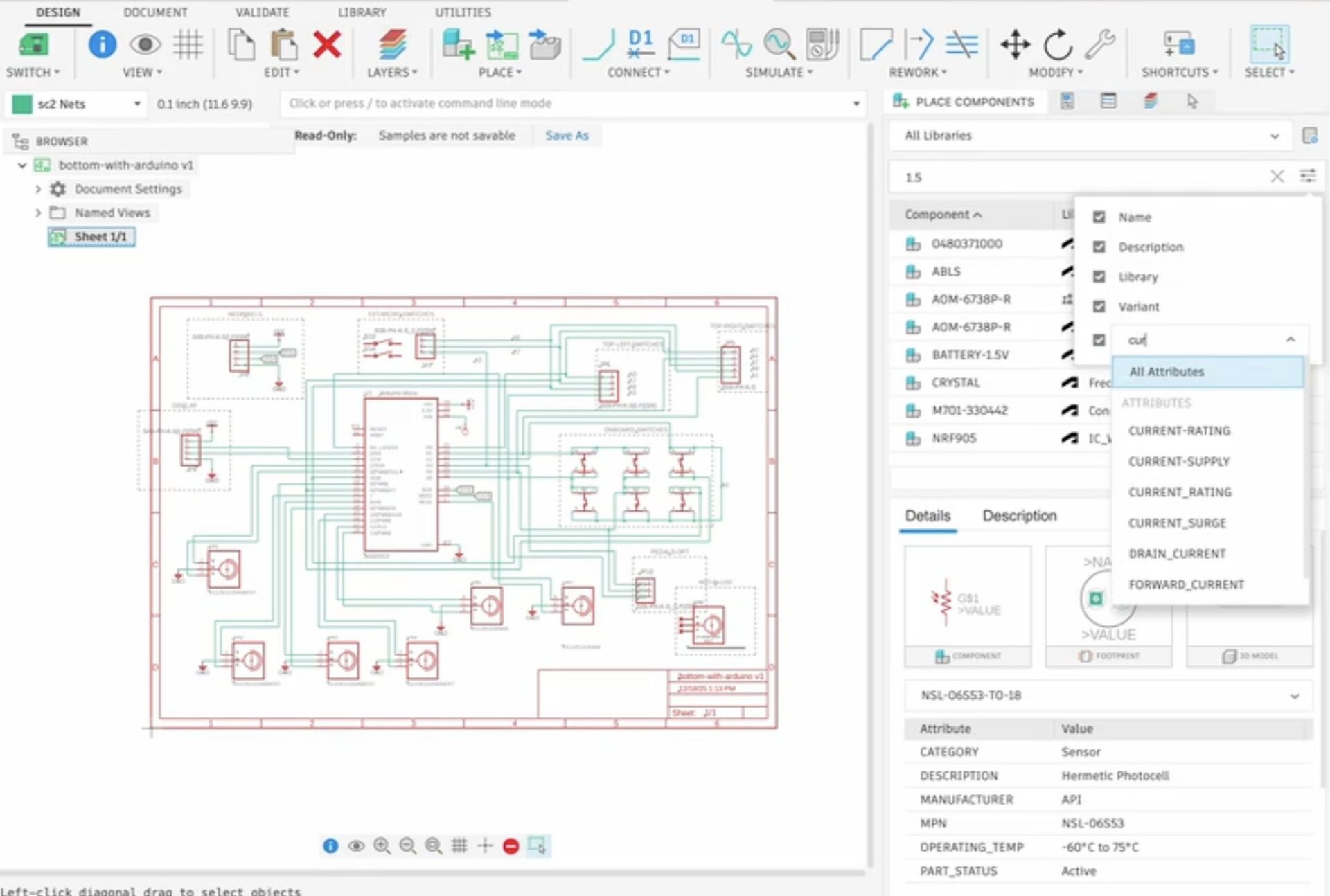
Electronics > Place > Place Components
You can now search by attribute values in the Place Panel to find the right components for your designs more quickly. The search box searches across all attributes by default. To narrow your results, use the search options dropdown to limit the search to specific attributes.
Attach Existing 3D Model to Footprint
Electronics > Library Editor
The “Attach Existing 3D Model” option now allows you to attach a STEP file or any design in your hub directly to a footprint. This automatically creates a single package for you, keeping your data panel clean and organized as you import STEP files.
Simulation
New Simulation Results Experience for LSS, Thermal and Thermal Stress
The post processing experience for Linear Static Stress, Thermal, and Thermal Stress studies has been modernized.
The updated interface delivers:
- Guided Safety Factor insights
- Consolidated result and legend controls
- A redesigned animation bar
- A unified cutting plane dialog
Note: The remaining structural simulation studies will continue to show the Classic Results experience. We plan to add this new experience to those studies in the future.
Results Guidance for Linear Static Stress study
A new guided visualization helps answer one of the most important questions in stress analysis: does the design meet the required minimum safety factor?
The Guided Results experience analyzes the result and provides information on what is happening, why it happened and gives recommendations on the possible next steps you can take to improve your results. Adjust safety factor values directly in the legend or results view and the guidance updates automatically, helping you iterate with confidence.
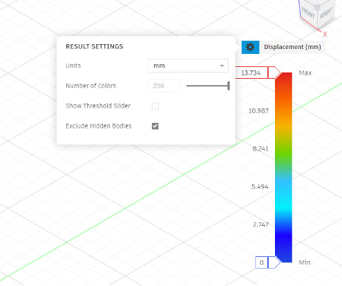
Result Settings and Legend Options
Result settings and legend controls are now consolidated and positioned directly next to the legend. Easily manipulate the legend as well as result settings to get a suitable visualization of your results.
New Animation Experience
Animation is now accessible through the animation bar at the bottom of the screen, replacing the previous command dialog workflow. There are also additional control options available now to improve the overall usability of animation for simulation results.
New Cutting Planes Experience
Additionally, there is now a new dialog for cutting planes, consistent with Injection Molding and Electronics Cooling simulation. You can now create and modify multiple cutting planes in the same dialog with additional controls available on styling and type of cutting planes.
Note: This new experience only allows you to use the central XY, YZ and ZX planes to create cutting planes. We will add the ability to create cutting planes using any point or surface on the model in the future.
Modernized Simulation Reports Format
We’ve heard your feedback on the updated report format introduced for Injection Molding, and we’re extending that experience to Linear Static Stress (LSS), Thermal, and Thermal Stress studies. The refreshed format offers a cleaner, more modern look along with additional customization options to help you better present and share your results.
Note: Reports in the new format are currently generated one study at a time. Support for creating a single report across multiple studies is coming in a future update.
New Compare Experience
Account > Preferences > Preview Features > Simulation
Welcome to a new experience in the Compare environment. This experience includes the existing capabilities of creating multiple views to compare multiple studies as well as syncing of cameras, result types and legend. But this is just the beginning, stay tuned as more capabilities will be made available for the Compare environment in the future.
Apart from the above-mentioned items, you will also notice improved experience in other areas of Simulation results as well for these 3 study types.
Additional Details
If you run into any issues with the new Simulation results experience for the Linear Static, Thermal and Thermal Stress studies, don’t worry, you still have the option to switch back to the classic results experience for these studies through User Preferences.
Manufacturing
New Intermediate Curves for Blend
When Stepover Calculation is set to From Tip of Tool and drive curves are defined explicitly, you can now define additional drive curves between the start and end drive curves to control how the blend progresses. This allows complex regions to be machined in a single toolpath when the start and end drive curves differ significantly.
These intermediate drive curves must correspond to surface edges within the machined region and be positioned between the start and end drive curves in the list of selected curves.
Toolpath Modifications for Roughing Strategies (MFG Extension)
You can now optimize 3D Adaptive and 3D Pocket toolpaths by applying modifications such as Trim, Delete Passes, and Leads and Links. When Trim or Delete Passes modifications require new leads and links, safeguards are applied to avoid plunges into stock. However, the resulting leads and links may not be optimal, such as the use of helical leads or full retraction links.
These results can be further refined by applying a Leads and Links modification, though this refinement considers the model only and does not account for the stock.
Note: This feature requires enabling the corresponding Optional Feature in the Preferences dialog. Edits may result in unexpected tool movements through the stock. Simulation and careful review of the results are strongly recommended.
Faster IPS Calculations
General > Manufacture > IPS and Remaining Stock > Processing Mode
A new preference is available that allows IPS and remaining stock calculations to run on the graphics processor. When set to Faster (graphics processor), subsequent calculations are performed on the GPU and may complete more quickly than the Standard option, depending on the GPU.
Learn more about Faster IPS Calculations.
Machine Auto-transparency
An Auto option has been added to the Transparent setting, available through the graphics toolbar under Machine Visibility and through the machine simulation dialog under Machine. When set to Auto, now the default, machine components that obscure the tool tip, or the center of the model when no tool is present, automatically become transparent when view rotation stops.
Learn more about Machine Auto-Transparency.
Additive Manufacturing
Multi-axis Rotations Added for True Shape Additive Arrangements.
We are excited to introduce multi-axis rotations for the True Shape arrangement methods in Additive Arrange. This rotates components around multiple axes sequentially, helping to find more orientations and often resulting in a higher packing density.
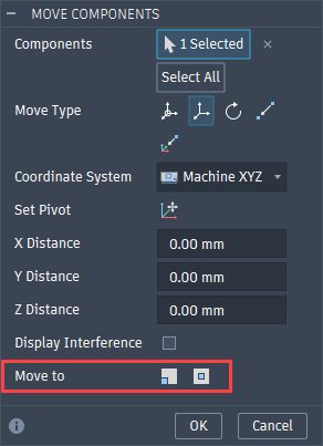
New Move to Corner/Center Move Command Options
Based on your feedback, we’ve replaced Move to Origin in the Additive Move command with two new options, Move to Corner and Move to Center. These additions give you greater control over how parts are positioned within the build volume, making it easier to place components exactly where you need them.
Component Pre-Selection
You are now able to preselect your components when using the Move, Duplicate, Remove from Setup, and Minimize Build Height commands. Using preselect you can select multiple components much easier with common selection tools such as rectangle select which is not available when Move, Duplicate, Remove from Setup, and Minimize Build Height commands are active.
Additional Enhancements
This release also includes a number of smaller enhancements and refinements across manufacturing workflows:
- The Deburr toolpath strategy has been updated to automatically remove excess points in cutting passes.
- Several small but impactful performance improvements have been made. When selecting large numbers of face contours using Select Same Face in operations such as 2D Contour, the dialog now responds more quickly when confirming the selection. Interactions with the Parameters table are also more efficient.
- Most numeric values in Manufacture now respect numeric precision, scientific notation, and trailing zeroes settings from the Unit and Value Display tab in Preferences.
- When selecting geometry for an operation, you can reference a geometry selection from another operation allowing you to reuse the machining boundary in another toolpath. Previously if you deleted the original operation, there was no indication that the machining boundary was linked by another operation. The original toolpath and its machining boundary were simply deleted, and the link to the new operation was lost. You would have to recreate the machining boundary for the new operation. Now if you try to delete an operation when the machining boundary is linked by another operation Fusion will show you a warning. You can still choose to delete the original operation but you now have the opportunity to cancel.
API
Reference Tools Available in the API
You can now select reference tools for operations that use them, via the API.
Insider Program
Do you want to engage more with the Autodesk community? Check out the Fusion Insider program to use exclusive previews, and test out the latest build before it’s released to the public.
As a member, you’ll gain inside knowledge of updates and a first look at new features. You’ll also be able to join exclusive events and try pre-release functionality. Plus, you can give feedback directly to the product teams.
Release Notes
To see more fixes, minor enhancements, and keep up with the latest check out our Release Notes for more information on changes to Fusion and Fusion web client.