Additive manufacturing is constantly evolving, but even advanced metal 3D printing methods like Metal Powder Bed Fusion (MPBF) come with hidden thermal challenges. Among them, heat concentration—especially in overhangs and small scan areas—can lead to defects such as oxidation, discoloration, or unwanted porosity.
Elevate your design and manufacturing processes with Autodesk Fusion
In this article, we’ll look at how the Autodesk additive manufacturing team used simulation and process control in Autodesk Fusion and Netfabb to identify high-temperature zones, optimize laser power at the voxel level, and significantly reduce hot spots in stainless steel builds.
Understanding the challenge
A common issue for users who print parts with MPBF is the buildup of thermal energy in certain areas of the part. The predominant area where this occurs is in overhangs, but it can also occur in parts with small layer scan areas. In both cases, there is a higher-than-normal energy density and a restriction in its dissipation.
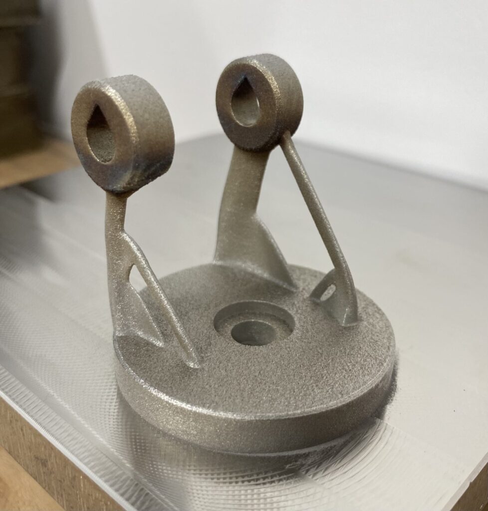
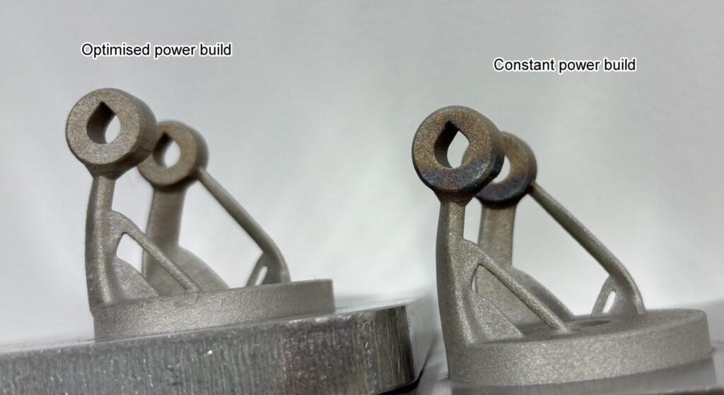
This causes visible defects like oxidation and discolouration, but can also cause physical ones like increased porosity and feature distortion. This is particularly the case with stainless steel, which has a relatively high melting point and a lower thermal conductivity. A great example of this is in the part below, where you can see the darker colours showing the oxidation and even some distortion on the corners of the rings.
Autodesk’s 3-step solution
Step 1: Identifying high temperature regions
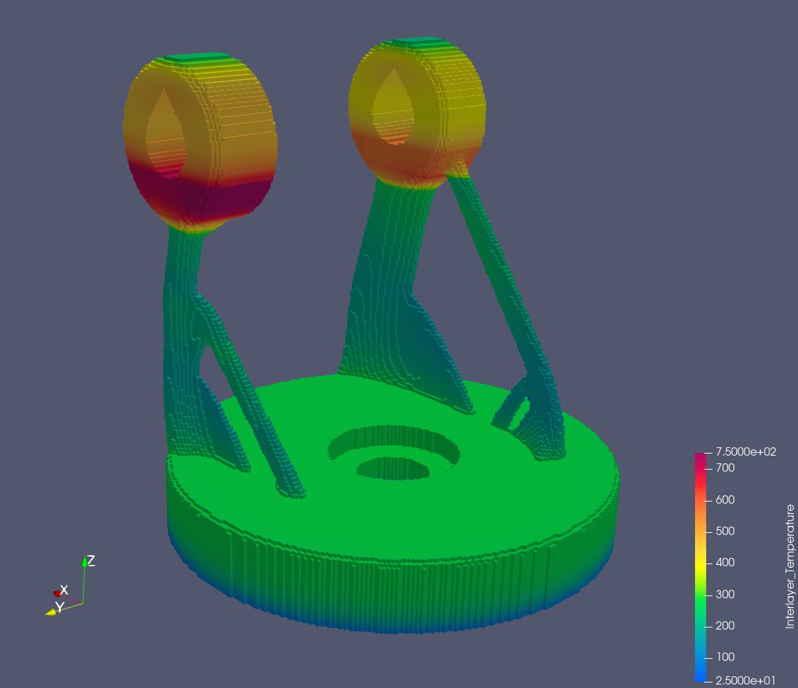
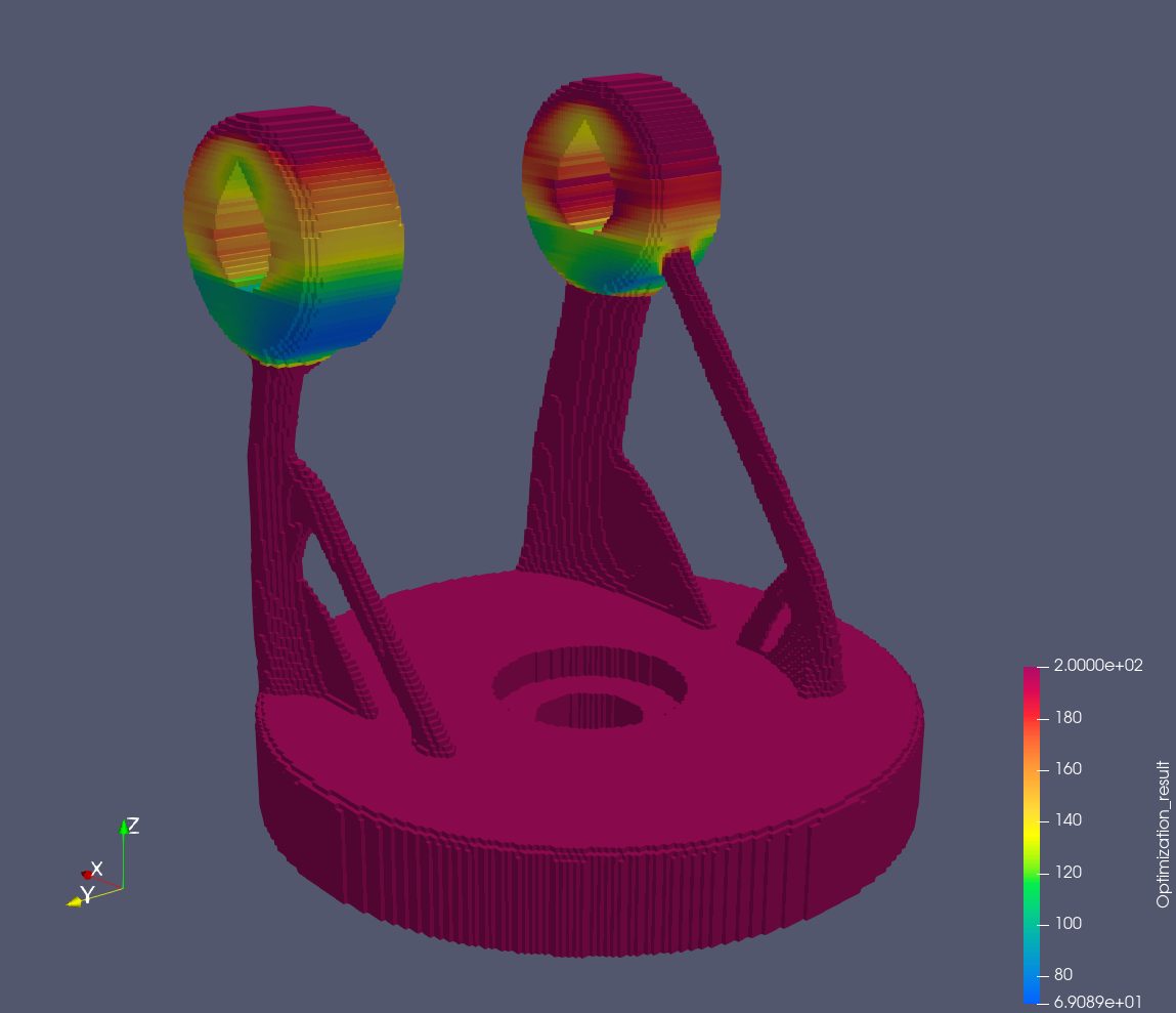
The first step is identifying where these high-temperature regions will be. Thankfully, with the MPBF process simulation tool we have in Fusion and Netfabb, users can simulate the build themselves to see where the thermal energy will be without having to actually run any builds. The image below shows the maximum temperature reached for each point during the build.
Step 2: Optimizing the laser power
Having identified the areas of heat build-up, the next step is to use this information to scale down the laser powers in these regions. We did this by defining a maximum temperature threshold for the build, and calculating the resulting laser powers on a per-voxel basis to not exceed this threshold. The image below shows how the laser power is scaled relative to the peak temperatures.
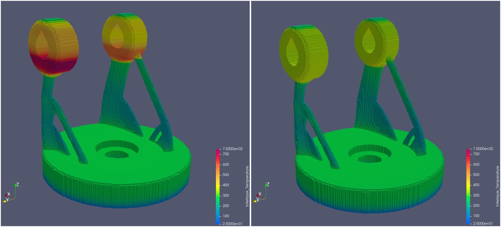
Below is a side-by-side simulation showing the maximum temperature reached for each point in the build. The image on the left is the non-optimised power build, and the one on the right is the power optimised build. You can see how the temperature peak is much lower in the rings.
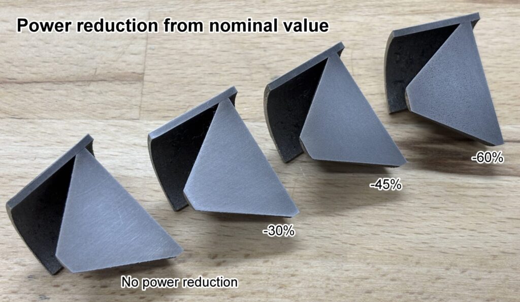
However, we had to be mindful that reducing laser power excessively can induce unwanted porosity and other adverse effects. Therefore, it was decided to run some test builds to check how different maximum power scaling values impacted porosity. The results showed substantial porosity in the builds that had a power reduction of up to 45% and 60% from the nominal value. However, no porosity was seen in the test builds for the 30% power reduction from the nominal value. We therefore proceeded by capping the maximum reduction of power at 30% of the nominal value.
Step 3: Toolpath generation
To apply the results of laser power optimization to laser path generation and create a build file, we used a project developed specifically for this purpose in Netfabb’s Advanced Toolpath Utility (ATU). Using voxel-based power scaling data, each generated exposure path segment is assigned a power value within the acceptable range (30% from the nominal value).
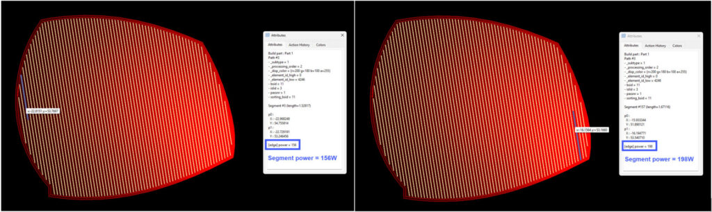
The video below shows the power scaling applied to each layer. Red represents nominal power, whereas black represents the 30% reduction from the nominal value of laser powers. Once the energy-optimized laser paths are generated, they are then prepared for the specific machine being used and written to a build file. Everything is now ready to start the build process.
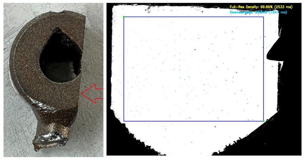
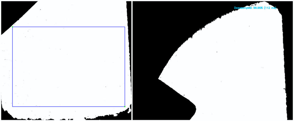
Analyzing the results
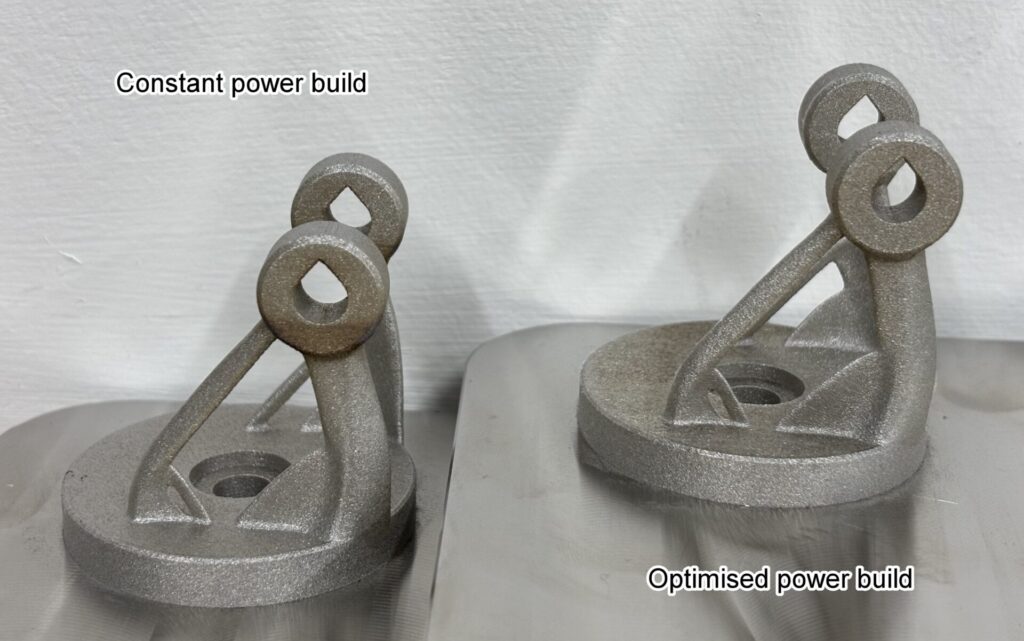
The result was very promising! We had a vastly improved visual result for the overhanging areas of the rings. Comparing the optimised power build with the non-optimised constant power build, there is a vast improvement in the oxidation and discolouration.
Finally, in collaboration with One Click Metal, we performed density measurements on both builds. The non-optimised sample achieved 99.96% density, compared to 99.84% for the optimised sample. This confirms that substantial quality improvements are possible with a marginal impact on porosity.