Learn how managing injection molding shrinkage it via design and simulations minimizes warpage and ensures quality and efficiency.
Shrinkage in injection molded parts is a fundamental challenge for mold engineers. It directly impacts dimensional accuracy, product quality, and manufacturing efficiency. Every type of plastic shrinks as it changes from molten to solid, and the rate and pattern of shrinkage can vary widely depending on the polymer, part design, and process settings. Understanding what drives shrinkage is essential for optimizing injection molding projects and producing parts that meet precise specifications.
What is shrinkage in injection molding?
Shrinkage in injection molding refers to the reduction in size that occurs when plastics cool and solidify. It happens at the molecular level and is influenced by factors, including:
- Polymer structure
- Fillers
- Fiber reinforcement
- Wall thickness
- Processing parameters
Shrinkage manifests as volumetric (overall change in volume) or linear (directional change), which can result in warpage, dimensional inaccuracies, and assembly issues.
Top 5 factors influencing the shrinkage of injection molded parts
1. Polymer type
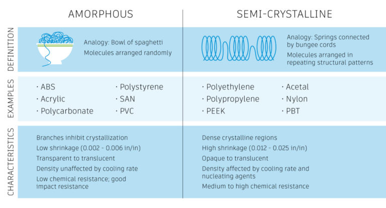
Amorphous polymers (e.g., ABS, polystyrene, polycarbonate)
Amorphous polymers have randomly entangled molecules, analogous to a bowl of spaghetti. During molding, molecules align in the flow direction yet relax back when cooled, resulting in mostly uniform shrinkage but with greater contraction along the flow direction.
Semi-crystalline polymers (e.g., PTFE, high-density polyethylene, isotactic polypropylene)
These feature ordered crystalline regions, like tightly bundled springs. When cooled, semi-crystalline polymers maintain flow alignment and significantly recrystallize, leading to higher shrinkage, especially perpendicular to flow. These materials can shrink more than amorphous plastics, affecting both density and dimensional stability.
2. Filler and fiber reinforcement
Filled/ reinforced materials (e.g., glass fiber, wood, mica): Introduced fibers don’t shrink with temperature change, which alters shrinkage behavior. Fiber orientation reduces shrinkage parallel to the fiber but increases it transversely. As a result, fiber-filled plastics may shrink less overall but could exhibit more differential shrinkage, impacting tolerance and dimensional reliability.
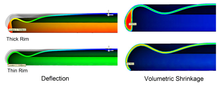
3. Wall thickness
Wall thickness directly affects cooling rate, crystallinity, and thus shrinkage:
- Thin walls cool and solidify faster, reducing shrinkage and crystallinity.
- Thick walls cool more slowly, increasing both crystallinity and shrinkage.
- Uniform wall thickness helps maintain consistent shrinkage and minimizes warpage—a critical tactic in part design.
4. Processing conditions
Key parameters to control include:
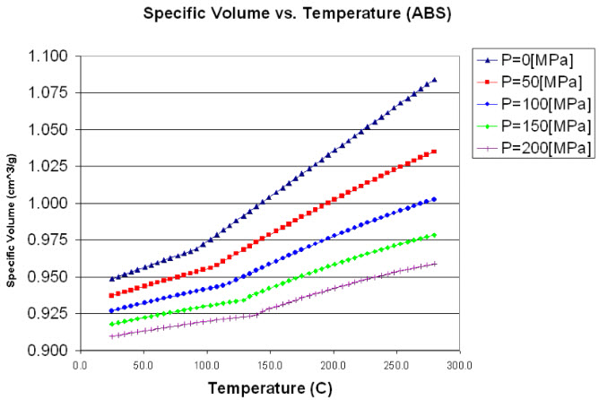
- Temperature: Higher melt temperatures increase shrinkage; controlling temperature can minimize contraction.
- Pressure: Adequate packing pressure can compensate for shrinkage by filling out features.
- Cooling rate: Faster cooling reduces crystallinity (and shrinkage) but can compromise mechanical performance; even cooling is crucial to avoid warpage.
- Gating strategy: Positioning gates from thick to thin areas ensures efficient packing and shrinkage management. Poor gating can cause uneven fill and shrinkage imbalances.
5. Part and mold design
Gate type and location, part geometry, and flow path all influence shrinkage distribution. Designers should consider flow orientation, mold scaling for nominal shrinkage, and location of mounting nodes—these can be modeled and validated to predict shrinkage in assembly conditions.
Shrinkage: Volumetric vs. linear
- Volumetric shrinkage: General contraction in all dimensions, primarily due to thermal cooling and crystallization. Can reach up to 25% depending on material and process.
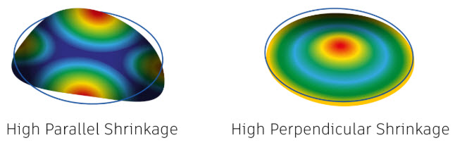
- Linear shrinkage: Predominantly directional, aligned with flow; influenced by molecular orientation during mold filling, gate location, and fiber content.
- Common warpage types due to shrinkage include “bowl” warpage (center pops up or sinks due to uneven perimeter cooling) and “saddle” warpage (center shrinks and buckles perimeter).
Advanced simulation for shrinkage prediction
Modern simulation tools such as Autodesk Moldflow allow engineers to visualize, analyze, and optimize shrinkage before tooling is built. These programs can model different materials, geometries, and process settings, providing actionable data on expected shrinkage and warpage. Running multiple scenarios in simulation accelerates design iteration and helps in selecting optimal parameters for material, mold design, and process setup—significantly reducing trial-and-error on the manufacturing floor.
Best practices for minimizing shrinkage in injection molding
- Choose the right polymer for dimensional needs.
- Design parts with uniform wall thickness.
- Optimize filler/fiber use for dimensional stability.
- Carefully control temperature, pressure, and cooling in the process.
- Use simulation tools for early shrinkage prediction and design validation.
Shrinkage is unavoidable in injection molding, but with expertise, smart design decisions, and modern simulation software, like Autodesk Moldflow its impact can be minimized—saving time, improving quality, and meeting project budgets.