Learn how Autodesk Inventor enhances mechanical design by streamlining the process, reducing tasks, and improving precision and efficiency.
Enhance Your Engineering Workflows
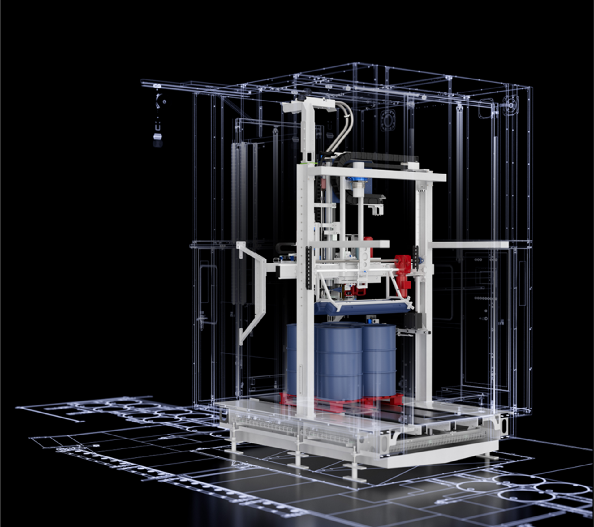
Precise, powerful, and ready for innovation with Autodesk Inventor.
Mechanical design is an intricate process that requires precision, foresight, and efficient use of tools. Autodesk Inventor is a powerful software that can significantly streamline this process if used effectively. Here are some strategies to accelerate your mechanical design using Autodesk Inventor.
Mechanical design strategies
Establish your starting point
When starting on a new machine design, it’s important to identify the main item around which the assembly will be built. In many cases, your design process begins with a model provided by a customer. This model becomes the core around which you build your machine. It’s essential to integrate this initial model efficiently, ensuring that all subsequent components align correctly and function as intended.
Working with planes
Planes can make your assemblies look messy and can quickly clutter your workspace, making the design process cumbersome. To maintain a clean and manageable design environment, it’s important to control the visibility of these planes. Here are 2 recommendations:
- Object visibility options: While you can turn off all planes using the object visibility options, this setting only lasts for the current session. A more effective approach is to turn off plane visibility as you create the assemblies.
- Naming key planes: To facilitate quick constraints without cluttering the workspace, name key planes in parts and assemblies. This makes them easy to identify and use later, streamlining the design process.
Skeletal modeling
Skeletal modeling is a technique that can significantly enhance the flexibility and stability of your design. A skeletal model contains planes, axes, and sketch geometry that serve as reference points for assembling the machine. Here are some benefits of skeletal modeling:
- Ease of constraints: Skeletal models are easy to constrain to, providing a stable framework for your design.
- Simplified changes: Changes are typically made to the skeletal model, rather than individual constraints. This simplifies modifications and ensures that they propagate correctly throughout the assembly.
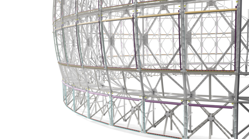
- Stability and efficiency: Skeletal models are stable and efficient, even in large assemblies. For example, Inventor user, Dynamic Attractions used skeletal modeling to design an observatory with two million components. Despite its complexity, the design process remained error-free and adaptable due to the skeletal modeling technique.
Movement in mechanical designs
When a sub-assembly is initially placed within an assembly, the parts contained within are fixed. This can limit the ability to visualize movement and interactions within the mechanism. However, by changing the sub-assembly to flexible, the assembly wrapper is ignored, allowing you to drag parts around or control them with constraints. This flexibility is incredibly useful for analyzing the movement of mechanisms within your machine design.
To enable flexibility in a sub-assembly:
- Select the sub-assembly: Right-click and choose the option to change it to flexible.
- Drive constraints: Right-click a parameter and select ‘Drive’ to control a constraint. Enter the start and end values in the drive dialogue and click play to preview the constraint. The position indicator will show the current value while the constraint is being driven.
This process allows for a more accurate and controlled way of testing your mechanism’s movement, providing a clearer understanding of how your sub-assemblies will perform within the larger assembly.
Design automation with iLogic
Design automation is a powerful way to save time and reduce repetitive tasks. iLogic, a rules-based design engine integrated into Inventor allows you to define rules to quickly reconfigure your designs. This is particularly beneficial for designs with numerous configurations. The intuitive interface of iLogic means that even users without advanced programming skills can create and implement rules, making it accessible to all Inventor users. Forms can also be used to fill out title blocks in drawings, significantly reducing the busy work that takes away from design time.
Performance optimization for mechanical design
Managing performance is extremely important in mechanical design, especially when working with large assemblies. Autodesk Inventor offers several features and best practices to optimize performance:
- Sub-assembly structure: Instead of placing all parts at the top level, plan a sub-assembly structure. This reduces the number of constraints at the top level, minimizes constraint issues, and allows multiple team members to work on different sections simultaneously.
- Express mode: For large assemblies, use express mode to load only the component cached graphics into memory, significantly speeding up the loading process.
- Simplify command: Use the simplify command to reduce the number and complexity of components in large assemblies. This command also allows the creation of substitute parts that remain associative to the original assembly, aiding in collaboration and BIM model creation.
Design accelerators
Design accelerators in Autodesk Inventor are essentially component generators and calculators for purchased components like shafts, fasteners, gears, belts, and pulleys. As an example, the synchronous belts tool, allows users to automate the creation of belt assemblies, pulley wheels, and idler arms. You can use existing components or let the tool generate new ones. By selecting the appropriate belt type and specifying a mid-plane, such as ‘key center’, Inventor provides a belt preview. Users can then define the belt width and select shafts for the pulleys, with customization options like adjusting the number of pulley teeth. Once set, Inventor creates and inserts the pulley and belt sub-assembly into the main assembly. This tool not only generates the entire assembly but also allows for easy modifications through the same interface used initially.
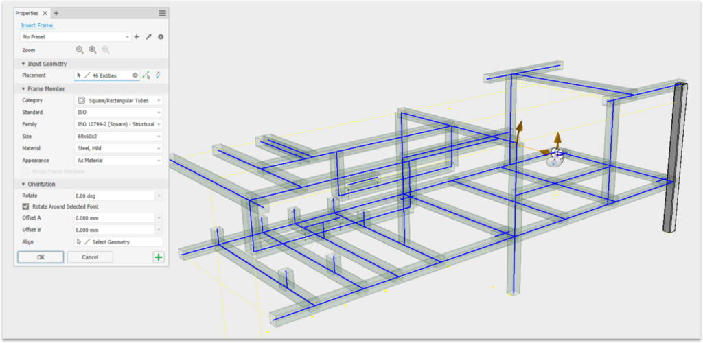
Frame generator
Traditionally, creating frames can be laborious, but Inventor’s frame generator simplifies this mechanical design process. It begins with a skeleton sketch, which serves as the framework’s foundation. You then select cross-sectional profiles to add to this sketch by picking lines or points. Customization is easy in the ‘frame m section, where you can choose members and apply various end treatments like miters or end caps. Right clicking a member allows you to edit its size while preserving end treatments. The point-to-point option helps bridge members between points, cutting them to the necessary length. You can quickly select multiple lines and disable unwanted reference lines. The Bill of Materials (BOM) displays each member’s length and total combined length, assisting in cut list creation and ERP ordering. The frame generator lets you customize profiles, sizes, and materials, and add finishes. It adjusts intersecting frames, resolves overlaps, and updates frame lengths when sketch dimensions change.
Model states
Model states in Inventor enables multiple representations of parts and assemblies within a single file. Each model state can feature different dimensions, components, and parameters, providing flexibility and efficiency. They support various workflows, from machining operations and product family creation to weldments and sheet metal stages. The finish feature, is also supported by model states, enhancing workflows like sheet metal bending. For example, a cardboard box can be represented in different folding stages using model states, starting from a flat net to the completed box by creating and managing states like ‘first fold,’ ‘second fold,’ and ‘third fold.’ In assemblies, these states can be accessed to show the box at various stages of packaging. This capability ensures detailed, accurate documentation and visualization, significantly improving design management and efficiency.
Mechanical design with Inventor
Autodesk Inventor offers a comprehensive suite of tools and features that significantly enhance the mechanical design process. Start accelerating your mechanical design processes, reducing repetitive tasks, and achieving higher design precision today.