
V.2.0.7830 – March 30, 2020
Manufacture
New! – Customize columns in the tool list (Preview)
Turn it on in Preferences > Preview features > Tool library
Found in Manufacture Workspace > Utilities > CAM Tool Library

You can now customize the columns in the tool list by selecting the settings icon at the top left. The drop-down settings panel allows you to add and remove columns using the checkboxes, as well as reorder the columns using the drag handles on the left-hand side of each column name.
New! – Apply holder to tools
We’ve added an option to apply the copied holder to the selected tools. To use this feature, copy a holder, select all the tools you would like to apply the holder to and then click the ‘Apply holder to tools’ button or right click > “Apply holder to tools’.
New! – Open edit page from cutting data list
We’ve added a way to go directly to the edit page for a cutting data preset from the main tool library page. Select the cutting data preset you would like to edit in the cutting data list and then click the ‘Edit preset’ button or right click > ‘Edit preset’.
We have also increased the reliability of the synchronization mechanism between files store in the “Assets” project and the local store of these data.
Modeling
Fixed: Joints issue when switching to Simulation or Generative Design
chill_wes001 as well as a number of other folks have reported an issue where joints in an assembly design created in the Design workspace become either lost or incorrectly placed when they switched to the Simulation or Generative Design workspaces. This is now fixed.
V.2.0.7824 – March 23, 2020
Electronics Design
- Some of you ran into issues with your Electronics Design documents not saving properly. Apparently modified schematics, 2DPCB files and library files were not being saved successfully if they were saved after Fusion 360’s auto-save happened. This is now fixed.
Usability
- Fusion 360 wasn’t able to install on a number of macOS machines running 10.13. Now it’ll install again without a hitch.
- We found an issue where some designs didn’t play nicely with the Bommer add-in, which resulted in an unexpected crash when you tried to work with both of them. We drilled to the bottom of this and got it sorted – no more crashes.
Manufacture
- In the Fused Filament Fabrication workflows, Fusion 360 was incorrectly showing 2 extruder heads when you only selected printers with a single extruder head. We fixed this issue so it shows the correct number of extruders as expected.
- We discovered some blank rows were generated in the print settings library of additive manufacturing. If you clicked Recent Folder and double clicked the blank rows, Fusion 360 refused to respond. This is now also fixed.
- There was an issue where toolpaths generated for metal 3D printing machines could not be exported. We got this sorted out and now you can export them again.
V.2.0.7813 – March 16, 2020
Manufacture
- We fixed an issue that was causing profile roughing gouges in a part ifuASTJY was working on. Now profile roughing should be back in tip-top shape.
- Some of you reported that you weren’t able to open Cam Pro posts; when you tried to open it, you received a “failed to open” error message. This is now fixed and you can open it again.
- Apparently when the post processing was using a machine configuration, the home positions were not used by the post processors. There was a bug in the machine definition usage; we got this sorted out and post processors now correctly use home positions again.
API
- william-c-ander
son discovered that debugging add-ins didn’t seem to work. Now it does.
V.2.0.7805 – March 10, 2020
[toc]
Data Management
[icon name=”star” class=”” unprefixed_class=””] New! Team Switcher in Data Panel
Expand the Data Panel and look at the top-left corner where it says your team or your name.
With Fusion 360, you can work by yourself or as a team. If you have multiple people collaborating with you on a project, you can setup a team account where you’ll have access to more permissions, role assignment, and who sees what. We’ve seen confusion around where to switch teams, how to switch teams, and what happens to your data when you do switch. The access point was not very discoverable nor was it descriptive.
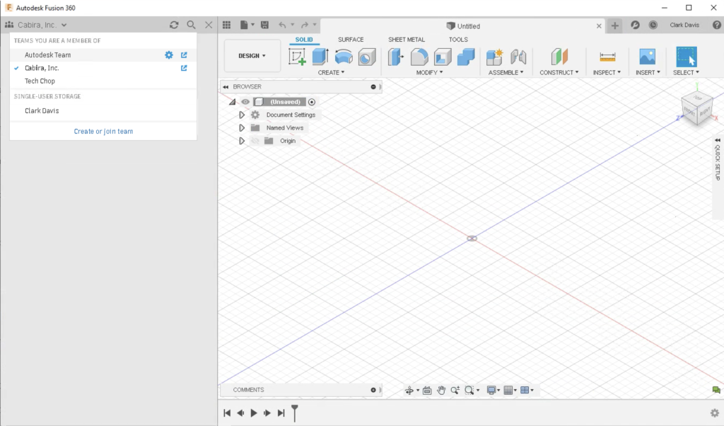
In this update, we’ve moved the access point to the data panel, so that it is more in context to where your data is. Changing teams will update the data panel, showing the respective projects within that team. Also for you eagle-eyes out there: the icon next to the team name changes depending on whether you are a team of 1 or a team of many.

We also made some minor (but very welcomed) tweaks to how you can view your projects on Fusion Team, via the data panel. Notice a new “view in web” icon to the right of your project – this will let you view details of your project on Fusion Team in your default web browser.
[icon name=”star” class=”” unprefixed_class=””] New! Overview and View tabs on Fusion Team
Data Panel > Project > Design > Design Version number > View Details on Web
Now when you go to view details of your design on Fusion Team via the web browser, you’ll notice two new tabs at the top left corner: Overview and View.
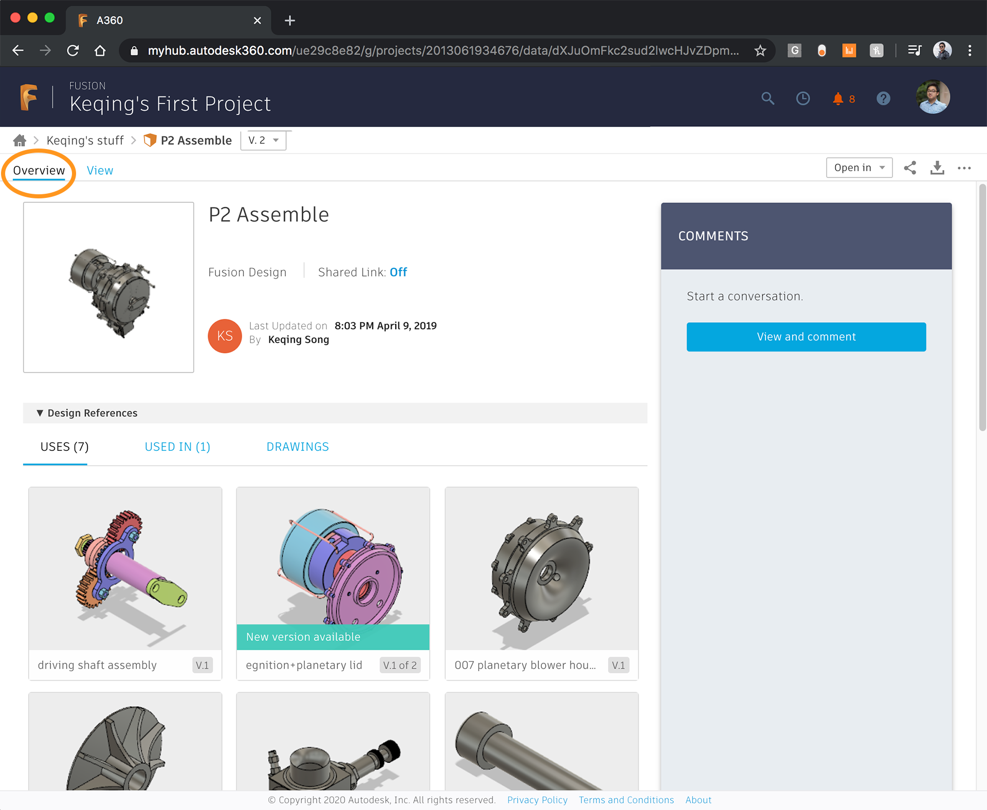
The Overview tab does exactly what it says: it gives you an overview of your design, with any design references, comments, or associated drawings.
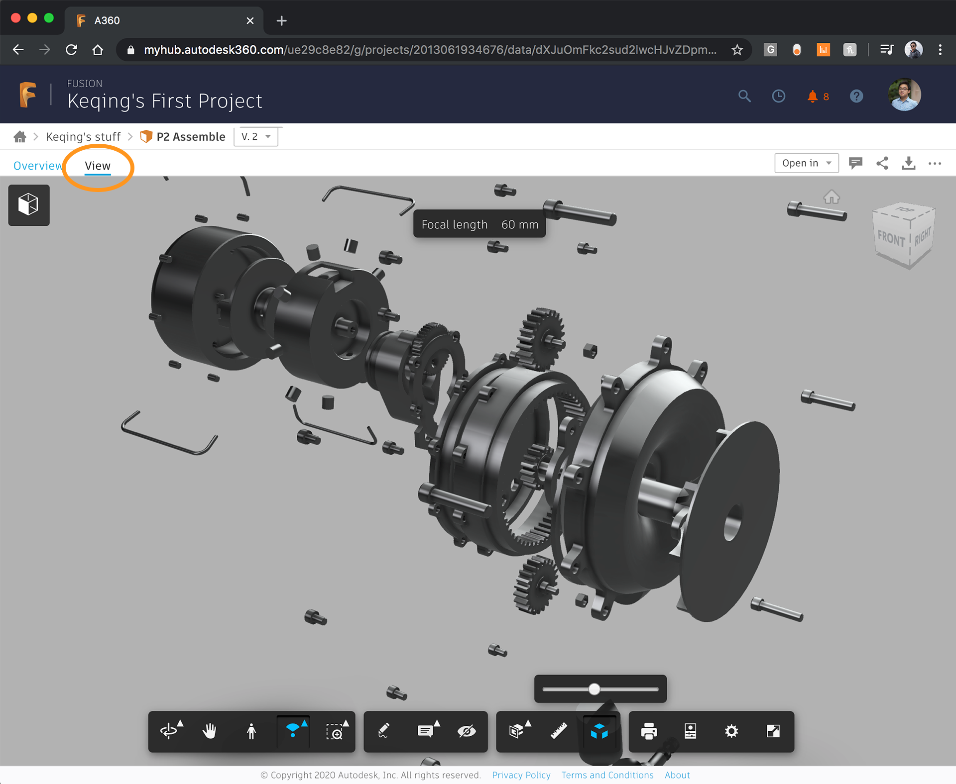
Toggle over to the View tab and you’ll see the design in a 3D web viewer. This is the same 3D viewer that existed before, but now it’s easier to access with it being right next to Overview.
[icon name=”file-text” class=”” unprefixed_class=””] Check out latest the blog post about Fusion Team
Sketching & Modeling
[icon name=”star” class=”” unprefixed_class=””] New! Intuitive 3D Sketching
Found in Create Sketch > Sketch Palette > 3D Sketch. Check the option to turn it on.
Experience the new behavior with these sketch commands: Line, Rectangle tools, Point, Spline tools, Circle tools, Conic Curve, Ellipse, and Polygon.

Previously if you wanted to create sketches in 3D, it was pretty cumbersome. In order to go from one plane to another, you had to sketch out the entity and then use the Move command to move it to another plane.

Now when you place the starting point of your sketch, you’ll immediately see origin axes, planes, and a set of familiar rotational manipulators appear as aids to your 3D sketch. Moving from one plane to another is as easy as moving your cursor in the direction you intend the sketch to go, and then inferred guidelines will appear to let you know where that sketch is going to be in 3D space.
—
[icon name=”star” class=”” unprefixed_class=””] New! Revamped Joint dialog and experience
Found in Design workspace > Assemble panel > Joint and Joint Origin

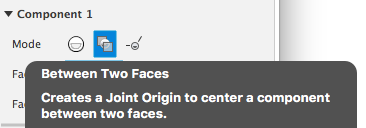
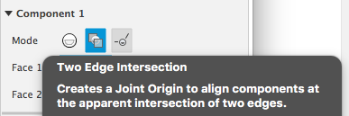
We’ve made some significant updates on how you would use joints. Now when you invoke the command, you’ll noticed a revamped dialog, with Position and Motion as separate tabs. In addition to selecting the components you’d like to join, you’ll also have the option to select the mode: Simple, Between Two Faces, or Two Edge Intersection.

A joint Between Two Faces was always doable in Fusion 360, but it was pretty hidden and not very discoverable. This new mode selection makes it as easy to create, as shown in the example below.

Two Edge Intersection mode is a brand new mode that enables you to create a joint or joint origin at the apparent intersection of 2 selected edges on 2 separate components. This new option should give you more flexibility around positioning components.
Check out learning concepts
See Joint dialog reference documentation
See Joint Origin dialog reference documentation
—
[icon name=”star” class=”” unprefixed_class=””] New! Edit in place for assemblies (preview)
Found in Preferences > Preview Features > Edit-in-Place
Access the functionality by hovering over inserted reference components, or when right-clicking the inserted reference component.

Previously when you wanted to edit a reference part within an assembly design, you’d have to open that part in a separate design document and do the editing there. This can be difficult depending on the complexity of the assembly, since you no longer see the part in context to the assembly as a whole. Now with Edit-in-Place functionality available as a preview, you’ll be able to edit a referenced part directly within the context of the overall assembly.

Notice that when you are in editing mode, the canvas perimeter is highlighted blue, letting you know that you’re editing a referenced part. A green checkmark with the name of the part will appear at the center, right below the toolbar, showing what part you are editing. Since the part is linked to the original design, you can also update the original part after you’re done editing the referenced one.
[icon name=”file-text” class=”” unprefixed_class=””] Check out the deep dive blog post
[icon name=”bullhorn” class=”” unprefixed_class=””] Got feedback about Edit-in-Place? Talk to us here.
—
[icon name=”star” class=”” unprefixed_class=””] New! Straighten tool in Form
Found in Create Form > Modify drop-down panel > Straighten
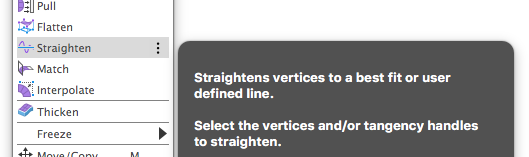
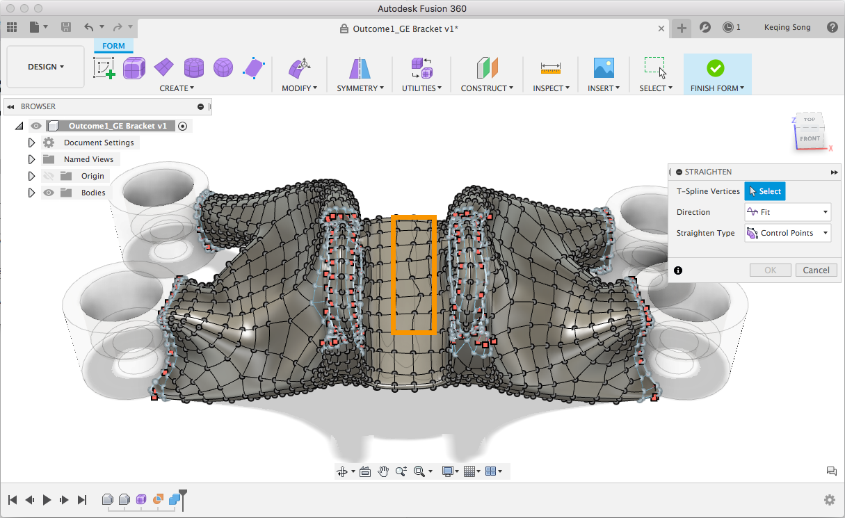
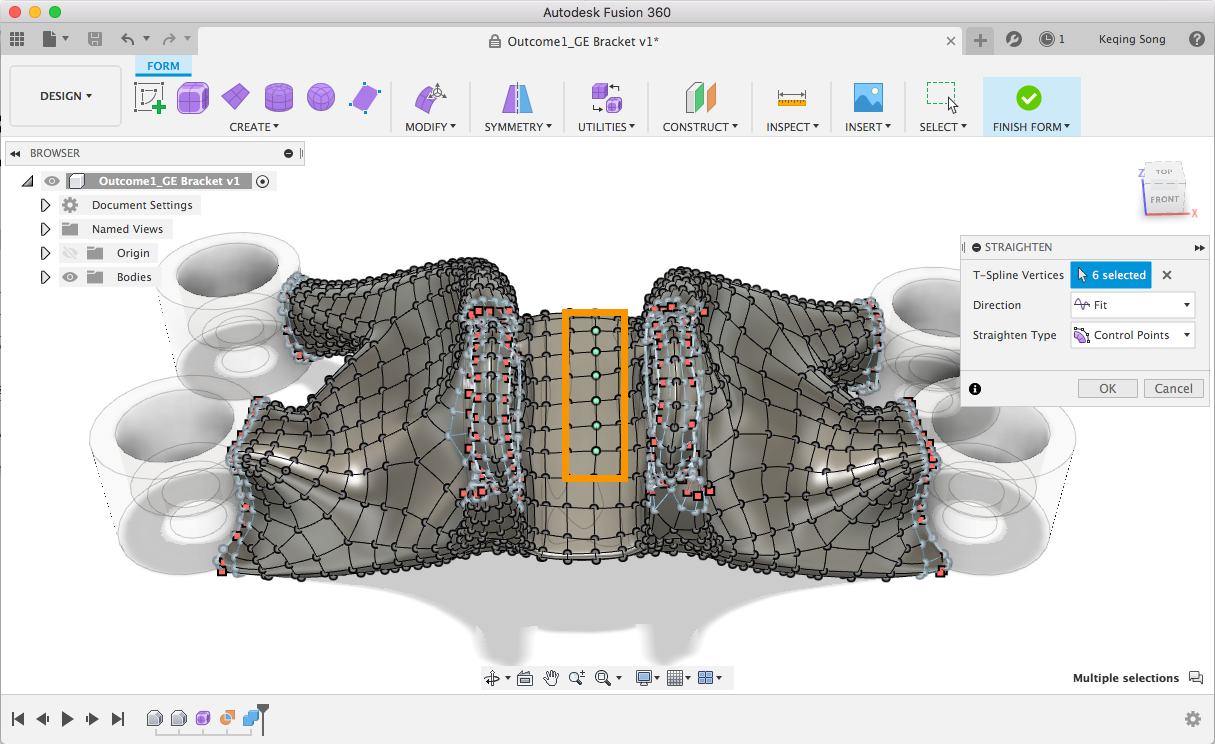
Previously if you’re working with T-Spline bodies and your edges aren’t as straight as you want them to be, you had to select the edge chain, drag one of the Edit Form manipulators, and set the value to 0, hoping that the edge will straighten. Now you can use this nifty Straighten tool to do the trick, with more options like Direction and Straighten Type.
See Straighten command reference documentation
—
[icon name=”heart” class=”” unprefixed_class=””] Improved! Fillet Performance
During testing, we found a bug that was causing performance issues when filleting edges. The bug was impacting how Fillet behaved when a large number of edges were selected to be filleted, causing Fusion 360 to react slower and slower. We’re happy to report that we’ve squashed this bug for good, and Fillet + selection performance is back to being responsive.
—
[expand title=”Customer Reported Issues Fixed – Click to expand“]
- teknoel told us about an issue we’ve been trying to nail down; the nav-bar at the bottom would sometimes remain on top even though Fusion 360 is in the back of other windows. Sorry for the inconvenience there, this has been fixed!
- We fixed an issue regarding Contact Sets being ignored when you tried to slide a component with a Slider Joint into another component. Sucker went straight through!
- Reported by TTechN: When overriding the bend radius, the specified value was not applied to all radii when symmetric sheet thickness is chosen.
- HughesTooling helped us uncover that the work we did to add more colors for component color cycling was only added to the default environment (Photobooth), and not the other environments. Now the new colors are available in all environments.
- We fixed an issue raised by zh275 where missing preserves in the Generative Design workspace were not marked “sick” after he modified the model.
- HenryDara told us about an issue where Fusion 360 came to a halt every time he tried to update his external references within his assembly design. We dug into this and found the culprit – this is now fixed.
- Lichtzeichenanlage found a bug where editing an existing pattern by inputting the exact same pattern instances in the field and then committing the pattern makes Fusion 360 unstable. We’re glad to say this has now been resolved.
- HughesTooling ran into an issue with the Press-Pull tool where Offset Faces no longer allowed more than one face to be added to a selection set when he held down CTRL or CMD. Turns out this was a bug we crushed a while ago, but apparently we didn’t crush it hard enough. Now we made sure it won’t come back.
- TrippyLighting found this bug while trying to help someone else – he discovered that projecting a face of a model with the sketch projection tool behaved differently in history modeling (with the timeline turned on) vs. direct modeling. We’re glad to report that we’ve ironed out the kinks and now the experience is consistent.
- Carsten.presser got an error message that said “UNDEFINED ERROR” when he was trying to create a sheet metal flange. We agree that this doesn’t help, so we updated the error message so that it’s more clear about what is actually happening.
- We fixed an old issue where using a referenced design in an assembly as the “Tool body” in the Combine command resulted in a compute error. Fast forward to now, we’ve finally resolved this issue and now the Combine will work properly!
- Another old issue that is now fixed – some of you experienced crashing when trying to open specific step files. Now they should all open in Fusion 360 without a hitch.
- We heard of weirdness around Compute All where doing it a few times will make component patterns disappear from the model, even though the action is still shown in the timeline. Apparently something got mixed up in the code, where visibility of the pattern instance was mistakenly turned off. Now it’s on, and things are back to normal.
- ncDBGCG called us out on a typo in the material library for the stainless steel 316L, where the Thermal Expansion Coefficient is set at 159 um/( m.°C) instead of 15.9. Whoops, our bad! Great catch – this is now fixed.
- Frankop and a few others noted an Insert Decal issue where, previously, a decal could be place on multiple selected faces. The issue made it so they were only able to put the decal on a single face, cutting off the decal when it hit the edge of another face. Now the decal behave is back to what it used to be.
- We fixed an issue that was reported a while back regarding derive workflows, where inserting a derived component into an assembly didn’t show up in the browser like it should. We made a number of fixes to how derive behaves with cross-referenced designs and we seemed to have squashed the bug.
- There were some fishy things going on when you tried to create a work plane from the face of a specific component. If the ingredients were right, you’d immediately seem an error, telling you that it can’t be done. We sorted this out so you can do this correctly.
[/expand]
Generative Design
[icon name=”heart” class=”” unprefixed_class=””] Improved! View Options in Generate and Solve dialog
Found in the View Options drop-down menu in Generate dialog

We added three options to manipulate dialog view: show solved studies, show studies with errors and show cloud credit costs & balances.
See the help documentation for Generative Design or for Simulation
—
[icon name=”heart” class=”” unprefixed_class=””] Improved! Explore performance when switching workspaces or documents
Found in Generative Design Workspace > Explore
We frequently heard you ask why Explore had to reload every time they switched between the Define and Explore, and also if you were going from document to document. Good news! Explore will no longer have to reload in either scenario. This should be a big time saver and all around better experience.
—
[expand title=”Additional Improvements – Click to expand“]
- Data Panel now shows appropriate description for generative outcomes
Now when you access your Generative Design outcomes from the data panel dive into the design history, you’ll see a short description that specifies that this design is a Generative Design Outcome, and not just any other T-Spline model. - Displacement limits now show a small glyph
We’ve made it easier to see where you have placed displacement limits by showing a small glyph in the appropriate area where a displacement limit was placed. Please note that this is only available in the Advanced Physics preview. - Scrollable outcome properties

As the constantly enriched list of outcome properties becomes longer and longer, we’ve added a scrollbar in the panel so you can scroll through the improved properties in Explore. - Also based on your feedback, we’ve improved pre-check messages for cost estimation so that they are more clear.
[/expand]
2D Drawings
Incorrect Quantity in Parts Lists issue fixed
We’ve gather a number of forum posts reporting that the quantity of your design parts in a parts lists shows incorrect numbers when you switched over to a different sheet in a 2D drawing. This is now fixed – please check your drawings again and let us know if you’re still seeing the issue.
Manufacture
[icon name=”star” class=”” unprefixed_class=””] New! Setup Sheet Viewer (for NC Programs)
Saving a setup sheet can be found in Actions tab.
Access a saved setup sheet from the data panel > project name or Fusion Team > project name.
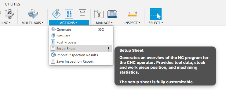

Now you can save a setup sheet in your Fusion 360 project, and access it via the data panel or Fusion Team. This new setup sheet style is a dynamic document viewable in a web browser from Fusion Team, and can be shared with teammates on the shop floor. Note that this is only for NC Programs.
—
[icon name=”star” class=”” unprefixed_class=””] New! Highlight Toolpaths in Canvas option
Found in Preferences > Manufacture > Highlight toolpaths in canvas
We’ve added a new option accessible in Preferences > General > Manufacture that turns on toolpath highlighting upon hover in the browser, intended to improve comparisons while programming.
With this option turned on, you’ll be able to hover over a toolpath in the browser and see the toolpath highlight, intended to improve comparisons while programming.
See the related learning documentation
—
[icon name=”star” class=”” unprefixed_class=””] New! 3D printing using Fused Filament Fabrication (FFF)
Found in Manufacture workspace > Additive tab

We have enabled 3D printing using Fused Filament Fabrication additive process. You can now prepare a 3D print for Single or Dual nozzle printers within the Manufacture workspace. Place and orient your model in the printer volume, choose from the list of predefined print settings or create your own before generating required supports and the output file you can take directly to the 3D printer. This first release includes support 20+ printers including Ultimaker, Bigrep, Prusa, Creality, XYZPrinting and Anet8. If you do not have any of the initially supported printers you can customize our generic printer to work with the printer you have.
Unlike other print preparation tools available in the market, the Additive Manufacturing functionality is a fully integrated part of Fusion 360. This means the setup is associative to the originating CAD model. Therefore, any changes made to the model in the Design workspace, will be reflected in the Manufacture workspace and the additive setup will always stay up to date with the latest version of the design.
[icon name=”video-camera” class=”” unprefixed_class=””] Watch the YouTube video
—
[icon name=”heart” class=”” unprefixed_class=””] Improved! Surface Inspection Results & Report (Extension Feature)
Found in Manufacture workspace > Actions panel drop-down menu
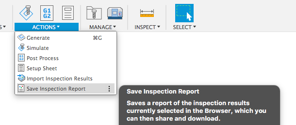
Surface inspection results are now calculated using projection of contact point on the CAD model, increasing the accuracy of results. We’ve made this the default behavior. We’ve added additional reporting capabilities to help you better use your inspection results. Right-clicking on the result folder, or selecting ‘Inspection Report’ from the Actions menu gives you the option to either save your results locally, or to Fusion Team for future access and analysis.
Additionally, you now can copy results from the Inspection Results dialog in a format that is consumable by Excel, allowing for easier reporting and analysis. Thanks for the feedback @motorsport_machinist!

See how to Calculate using projection
—
[icon name=”heart” class=”” unprefixed_class=””] Improved! 2D Bore: “Keep Tool Down” option
Found in Manufacture workspace > Milling tab > 2D panel drop-down > Bore

When using 2D Bore with Finishing Passes, the tool retracts between the ramping and the finishing passes. We’ve added an option to Keep the Tool Down between passes per @Steinwerks’ request.
—
[icon name=”heart” class=”” unprefixed_class=””] Improved! Turning Profile Roughing – Retraction Policy

A new parameter “Retraction Policy” was added to the Linking tab of Turning Profile Roughing operations. This parameter is only available for Inside Profiling mode when the cycle is set to Horizontal Passes and the machining direction is set from Front to Back. This parameter is not available when the Use Canned Cycles parameter is checked on. When Retraction Policy is set to Minimum Retraction, the tool retracts minimally in Z after every cutting pass up to the Z Clearance value (existing behavior). When this parameter is set to Full Retraction, the tool retracts to Safe Z after every cutting pass (new behavior).
The benefit here is that when you are boring deep holes or machining a material that produces stringy chips, it is preferable to allow the boring tool to retract farther than the Z clearance up to the Safe Z coordinate after every cutting pass. This allows chips to exit the hole more cleanly, thus reducing the possibility of a chip tangle forming inside the hole.
—
[expand title=”Customer Reported Issues Fixed – Click to expand“]
- Sync Visibility – Show ‘From solid’ stock – We’ve heard that while usually a helpful little feature, the ‘Sync visibility’ option is going overboard and hiding the stock when Stock mode is set to ‘From solid’. This should be fixed in this release.
- Machine Configurations Error: Invalid machine configuration in toolpath- We fixed an issue @Lonnie.Cady alerted us to where valid machine kinematics definitions threw erroneous errors.
- We fixed a bug with turning profile roughing operations where the toolpath limits were not matching the turning profile finishing limits if the limits were set to “contact point”.
- Some of you reported problems with both turning profile roughing and finishing boring operations where the tool was retracting to an unsafe point below the clearance radius. This is now fixed.
- Apparently when a setup having multiple turning profile roughing canned cycle operations would not generate NC code. We got this resolved as well.
- We fixed a problem with turning profile finishing toolpaths with multiple stepovers where every stepover other than the final one was violating the Z and X limits.
- BobVawter went full-on detective mode and found an issue where reorganizing NC comments and adding operations to the various setups caused Fusion 360 to become very unstable. We looking into this and got it sorted out.
- We fixed a Cutting > 2D Profile toolpath issue where the toolpath under geometry has been set to Outer loops, with three contours selected for machining, however the generated toolpath only has passes for one contour.
- We were told that Fusion 360 hung indefinitely when you tried to edit a Scallop operation on a specific file you sent us. We believe this issue is gone, please check again and let us know if you still experience any slowness.
- andrewbarton reported an issue where Fusion 360 got really paranoid and froze when he tried to regenerate all of his toolpaths in a single sweep (instead of one by one) in the Manufacture workspace. We’re glad to report back and say that we’ve fixed this issue!
- We updated our kernel and fixed an issue with gouging for certain turning profile roughing toolpaths with vertical passes using a neutral holder.
- pawel.piela1 asked us how he would setup minimum cutting depth on a lathe, and the answer is even depths of cut for profile roughing, which is now available.
- CAMXPRESS posted about an Invalid machine configuration in toolpath issue back in September of last year. This is now resolved.
- We got word that some of your experienced a “Warning: Current tool orientation is not supported from the selected machine” message with head-head machine configurations in Fusion 360. It was incorrectly claiming that the tool orientation is not supported for the selected machine, however a toolpath is calculated and marked with a warning. now it calculates correctly with no issues.
[/expand]
API
[icon name=”star” class=”” unprefixed_class=””] New! Create your own tab in the toolbar
Sample script found in Product Documentation > Programming Interface > Fusion 360 API User’s Manual > Sample Programs > User Interface > General

Last year we went through an UI modernization project where we’ve introduced tabs in the toolbar to better scale with Fusion 360 as we continue to mature the software. If you’re writing add-ins for Fusion 360 and have added custom commands to the toolbar, you’ve probably noticed that some of those commands have been placed in tabs that you may or may not agree with. Now you have the ability to better organize them by creating a custom tab in the toolbar. Your new tab will sit next to the last tab in the toolbar.
We’ve provided a sample API in the Sample Programs section of our Product Documentation for you to use as reference.
[icon name=”file-code-o” class=”” unprefixed_class=””] Get the Sample Script