Learn how to analyze a complex electrical circuit to find voltages of currents with Kirchhoff’s Current Law and Voltage Law.
Ohm’s Law is your golden ticket for calculating the voltage, current, or resistance in a simple series or parallel circuit, but what happens when your circuit is more complicated? You might be designing electronics that have both parallel and series resistance, and Ohm’s Law starts to fall down. In such cases, a circuit diagram becomes essential for visualizing the arrangement of components and understanding how current and voltage are distributed throughout the circuit. Or what if you don’t have a constant current source? In these situations, when you can’t only use V = IR, it’s time to stand on the shoulders of Ohm and use Kirchhoff’s Circuit Law. Here we’ll be looking at what Kirchhoff’s Circuit Law is and how to use it to analyze the voltage and current of complex electrical circuits. Kirchhoff’s Laws are a basic tool in electrical engineering, providing the foundation for analyzing and solving circuits of any complexity.
Elevate your design and manufacturing processes with Autodesk Fusion
What is Kirchhoff’s Circuit Law?
When you’re building a complex circuit that includes bridges or T networks, then you can’t solely rely on Ohm’s Law to find the voltage or current. This is where Kirchhoff’s Circuit Law comes in handy, which allows you to calculate the current and voltage for complex circuits with a system of linear equations. There are two variations of Kirchhoff’s Law, including:
- Kirchhoff’s Current Law: To analyze the total current for a complex circuit
- Kirchhoff’s Voltage Law: To analyze the total voltage for a complex circuit
- When you combine these two laws, you get Kirchhoff’s Circuit Law
In circuits that contain two loops or more, both Kirchhoff’s Current Law and Kirchhoff’s Voltage Law are applied to analyze current and voltage throughout the network.
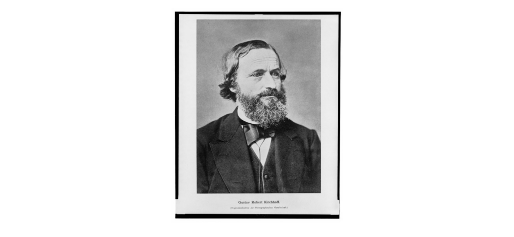
Like any other scientific or mathematical law named after its creator, Kirchhoff’s Circuit Law was invented by German Physicist Gustav Kirchhoff. Gustav was known for many achievements in his lifetime, including the theory of spectrum analysis, which proved that elements give off a unique light pattern when heated. When Kirchhoff and chemist Robert Bunsen analyzed these light patterns through a prism, they discovered that each element in the periodic table has its own unique wavelength. The discovery of this pattern allowed the duo to uncover two new elements, cesium, and rubidium.
Kirchhoff later went on to apply his spectrum analysis theory to study the composition of the sun, where he discovered many dark lines in the sun’s wavelength spectrum. This was caused by gas from the sun absorbing specific wavelengths of light, and this discovery marked the beginning of a new age of research and exploration in the field of astronomy.
A bit closer to home in the world of electronics, Kirchhoff announced his set of laws for analyzing the current and voltage for electrical circuits in 1845, known today as Kirchhoff’s Circuit Law. This work builds upon the foundation outlined in Ohm’s Law and has helped pave the way for the complex circuit analysis that we rely on today.
Understanding Volate Sources
Voltage sources are the heart of any electrical circuit, providing the driving force that pushes electric current through the various circuit elements. Whether you’re working with a simple battery or a sophisticated power supply, the voltage source establishes the potential difference needed for current to flow through the components and wires connecting your circuit. In the context of Kirchhoff’s laws, understanding how voltage sources interact with other components is essential for accurate circuit analysis.
When you apply Kirchhoff’s voltage law (also known as the voltage law or loop rule), you must account for every voltage source in the circuit. Each voltage source contributes a voltage rise, which is balanced by the voltage drops across resistors and other components as you move around a closed loop. This balance ensures that the algebraic sum of all voltages in any closed loop is equal to zero, a fundamental principle for analyzing both simple and complex circuits.
Voltage sources can be found in all types of circuits, from basic DC circuits powered by a single battery to more complex AC circuits with multiple voltage sources and loads. By carefully considering the placement and value of each voltage source, you can predict how current will flow and how voltages will be distributed across the circuit. This understanding is crucial when you start analyzing circuits using Kirchhoff’s laws, as it allows you to solve for unknown values and design circuits that perform as intended.
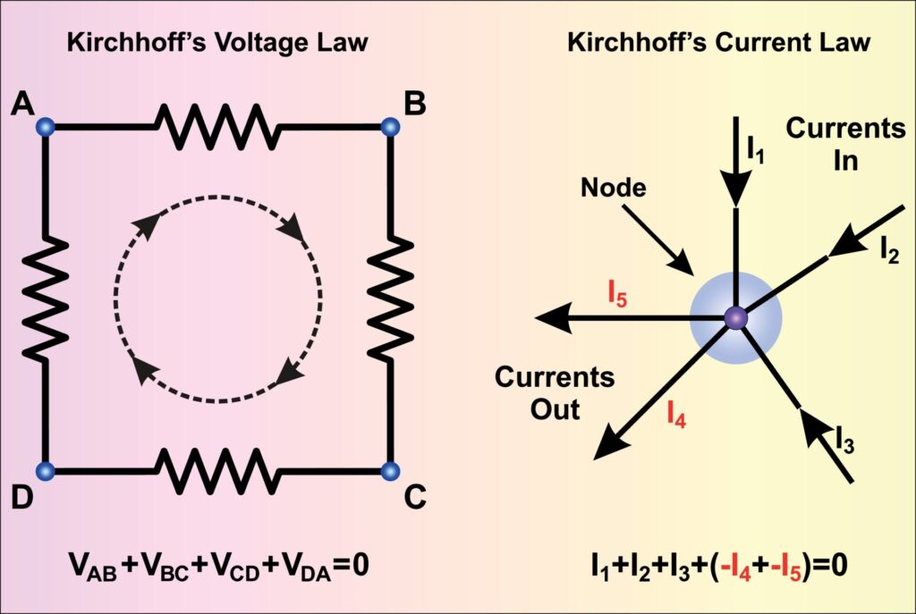
Kirchhoff’s Current Law
Kirchhoff’s Current Law states that the amount of current that enters a node equals the amount of current leaving a node. Why? Because when current enters a node, it has no other place to go except to exit. What goes in must come out. You can identify a node where two or more paths are connected via a common point. In a schematic, this will be the junction dot connecting two intersecting net connections. When using Kirchoff’s Current Law, keep in mind that everything has to balance out, a principle Kirchhoff called the Conservation of Charge.
To validate Kirchoff’s Current Law in a circuit, follow these three steps:
- Calculate the total current of the circuit
- Calculate the current flowing through each node
- Compare input and output currents at specific nodes to validate Kirchoff’s Current Law.
In more complex circuits, you may encounter specific nodes such as node B or junction E, where you apply Kirchhoff’s current law to analyze the currents flowing through each branch.
1. Calculate the total current
Start by using Ohm’s Law to get the total current of our circuit with I = V/R. We already have our total voltage, and now we just need to find the total resistance in all of our nodes. This requires the simple method of calculating the total resistance of resistors wired in parallel.
Once you have your total resistance for the entire circuit, plug it into Ohm’s Law I = V/R to get the total current in our circuit.
2. Calculate node currents
Now that we know how many amps are flowing out of our circuit, we can calculate the current at each set of nodes. We’ll again enlist the help of Ohm’s Law in the form of I = V/R to get the current for each node branch.
3. Validate Kirchhoff’s Current Law
With the current for each node branch calculated, we now have two distinct reference points that we can use to compare our input and output currents. This will allow us to analyze our circuit and validate Kirchhoff’s Current Law.
Kirchhoff’s Voltage Law
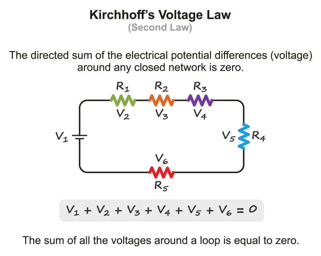
Kirchhoff’s Voltage Law states that in any closed-loop circuit, the total voltage will always equal the sum of all the voltage drops within the loop. You’ll find voltage drops occurring whenever current flows through a passive component like a resistor, and Kirchhoff referred to this law as the Conservation of Energy. Again, what goes in must come out.
When applying Kirchhoff’s Voltage Law, you analyze loops in the circuit. The loop starts at a chosen point and proceeds in a specified direction, either clockwise or counterclockwise. It is important to maintain the same direction throughout the loop to ensure correct voltage summation. The directions you choose for current flow and voltage arrows must be consistent. If you traverse a component in the direction opposite to the current flow, the voltage drop is considered negative; if you go in the same direction as the current, the voltage drop is positive. This sign convention helps determine the actual direction and polarity of voltages and currents in the circuit.
If your circuits’ passive components are connected in series, you can simply add the total voltage drops together and compare it to the total voltage to validate the law. Since the total voltage drop in the circuit has to equal the total voltage source, this provides an easy way to calculate our missing variable. If you wanted to express this relationship as a proper algebraic expression, you’d get the sum of all voltage drops and the total voltage equalling zero, as shown here:
Ohm’s Law is often used together with Kirchhoff’s Law to analyze current flow and voltage drops in the circuit. This combination allows you to solve for unknown currents and voltages throughout the loops.
Typically you’ll need to take the following steps to validate Kirchoff’s Voltage Law:
- Calculate the total resistance of the circuit
- Calculate the total current of the circuit
- Calculate the current through each resistor
- Calculate the voltage drop across each resistor
Compare the voltage source to the total voltage drop to validate Kirchoff’s Voltage Law
1. Calculate the total resistance
If all of your resistors are wired in series, you can easily find the total resistance by just adding all of the resistance values together. This total resistance is also known as the equivalent resistance of the series circuit.
2. Calculate the total current
Now that we know our total resistance, we can again use Ohm’s Law to get the total current of our circuit in the form of I = V/R, which looks like this: This is an example of setting up an equation to solve for the total current in the circuit.
3. Calculate the current through each resistor
If all of your resistors are wired in series, they‘ wi‘ll all have the same amount of current flowing through them, which we can express as:
This approach can also be applied to individual components in the circuit, such as resistors, capacitors, and inductors, by using the equations specific to each individual component.
4. Calculate the voltage drop across each resistor
Our final calculation will again use Ohm’s Law to give us the total voltage drop for each resistor in the form of V = IR, which looks like this:
A negative sign in the result indicates that the voltage drop is in the direction opposite to the chosen reference direction.
5. Validate Kirchoff’s Voltage Law
To see Kirchhoff’s voltage law in action, let’s walk through a practical example using a simple series circuit. Imagine you have a circuit with a single voltage source—a 12V battery—and three resistors: 2Ω, 3Ω, and 5Ω, all connected in series. The voltage source provides the energy, and as current flows through each resistor, a voltage drop occurs across each one.
First, calculate the total resistance in the circuit by adding up the resistances: 2Ω + 3Ω + 5Ω = 10Ω. Next, use Ohm’s law to find the current flowing through the circuit: I = V/R = 12V/10Ω = 1.2A. Since the resistors are in series, the same current flows through each resistor.
Now we have all of the data we need, including the total voltage of our circuit, along with each voltage drop across each of our resistors. When putting all of this together, we can easily validate Kirchhoff’s Voltage Law. The total voltage equals the total voltage drop in our circuit. This validation is performed by summing the voltages around all loops in the circuit. What goes in must come out, and Kirchoff’s Law works yet again!
Process for Using Kirchhoff’s Circuit Law
With an understanding of how Kirchhoff’s Circuit Law works, you now have a new tool in your toolbox for analyzing voltage and current in complete circuits. When using these Laws out in the wild, consider using the following step-by-step process:
- First, begin by labeling all of the known voltages and resistances on your circuit.
- Then name each branch on your circuit with a current label, such as I1, I2, I3, etc. A branch is a single or group of components connected between two nodes.
- Next, find Kirchhoff’s Current Law for each node in your circuit.
- Then find Kirchhoff’s Voltage Law for each independent loop in your circuit.
Once you have Kirchoff’s Current and Voltage Laws calculated, you can then use your equations to find any missing currents. Ready to try it on your own? Take a look at the circuit below and see if you can validate Kirchoff’s Current Law and Voltage Law with a little bit of help from Ohm!
Standing on the shoulders of Ohm
With Kirchhoff’s Circuit Law in hand, you now have all the tools you need to analyze the voltage and current for complex circuits. Like many other scientific and mathematical principles, Kirchhoff’s Law stands on the shoulders of what came before it – Ohm’s Law. You’ll find yourself using Ohm’s Law to calculate individual resistances, voltages, or currents and then building upon these calculations with Kirchhoff’s Law to see if your circuit holds true to these Current and Voltage principles.
Ready to apply Kirchhoff’s Law in your own electronics design project? Try Autodesk Fusion for free today!