
It was one of the first things we were taught in my high school drafting class. Just as it is today, linetypes are a core feature of proper drafting. I can still remember picking up that freshly pointed HB pencil and gliding it against my T-Square, while properly rolling it along the way to ensure an even line.
The point is, we were the drafter, and we were responsible for knowing what to do, what type of line to use, and correctly applying that skill. A skill which in the world of CAD is generally rendered moot.
But that’s OK. This is one of those posts where, if your CAD department is set up correctly, most users will never need to load and manage linetypes. I know my users never did. So, while it is, as I said, a core feature, I’ll go over the basics first, then jump into a cool tip that makes creating your own custom linetypes easy. This isn’t called Tuesday Tips for nothing!
A Linetypes Primer
If you start a new drawing using the acad.dwt template file, you’ll get three linetypes: ByLayer, ByBlock, and Continuous. To get more, you have to load them. Launch the Linetype Manager dialog by selecting the Other option in the Linetype pulldown menu in the Properties panel of the Home tab of the ribbon. Or type in LT. Your choice.
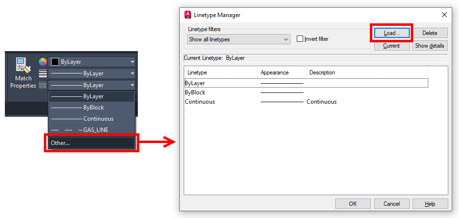
The next step is to click on the Load button. Doing so will display the Load or Reload dialog as shown below. Each type will have a name, a description that may better explain the linetype, and a graphic representation of what it looks like.
Select the linetype you want, and click OK. It will now display in the Linetype Manager list, available for you to use in your current drawing. Again, you may have never actually done this, as it should have already been done for you. But now you know.
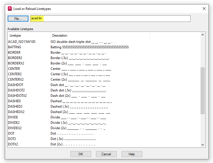
Notice the dialog wants you to select a file, and defaults to something called “acad.lin”. The acad.lin file is simply a text file containing all of the linetype definitions. Let’s explore that file a little closer.
The ACAD.lin File
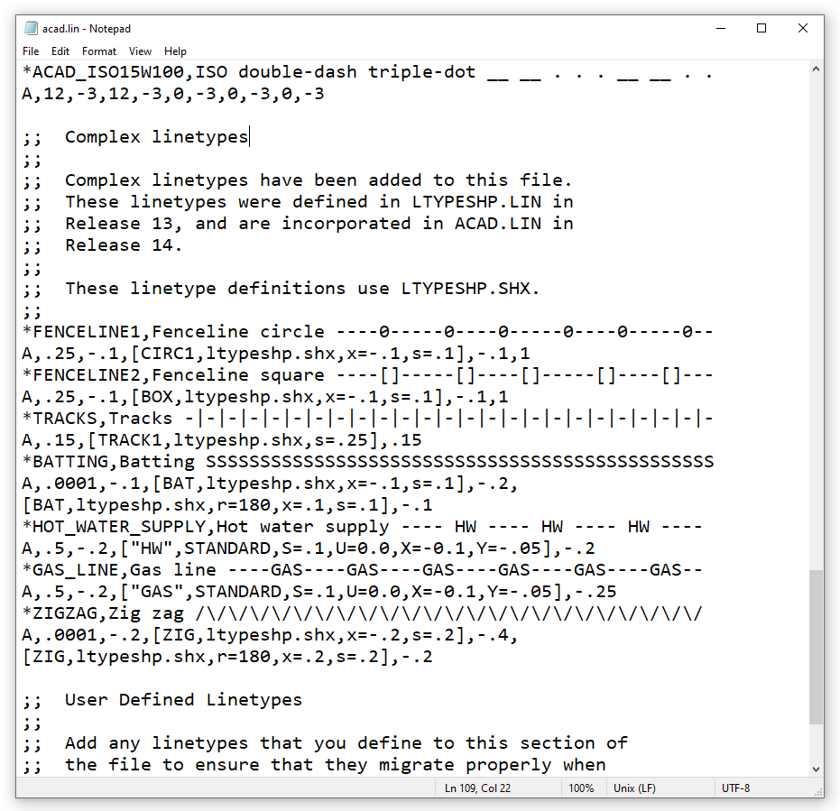
AutoCAD has two such files, the other being “acadiso.lin” for use in isometric drawings. They are stored in, and loaded from a folder in your user profile. More on that in a minute. Below is an image showing what it looks like. I’ve scrolled down a bit, mostly to show some comments referencing Release 13 and 14, but also to show the more complex linetype definitions.
Let’s look at the definition for GAS_LINE, as we’ll be using that an example for the tip part of this post. You have the name and description – including the graphic representation – followed on the next line by the rather cryptic definition of how the linetype is created. Trust me, you do not want to learn how to define these things. Check out the ACAD_ISO… definition at the top of the image. I’m sure that the definition of “A,12,-3,12,-3,0,-3,0,-3,0,-3” makes total sense to you. Yeah, me too.
The Actual Tip: Creating Your Own Linetypes
By my count, there are 45 linetypes defined in the acad.lin file. Surely that’s enough to cover every situation ever imaginable, right? Of course not. But having just filled you in on how they’re defined, where would you even start if you had to create a custom linetype?
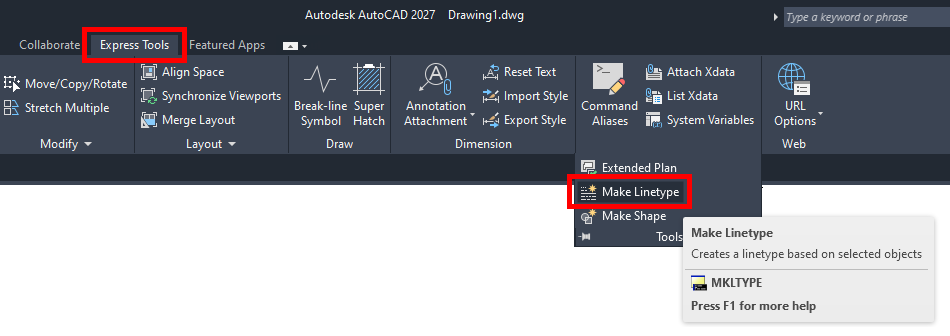
That’s where AutoCAD’s Express Tools saves the day. Tucked safely away in the Additional Commands menu of the ET Tools panel, you’ll find Make Linetype.
Let’s say we need to make the following (beautiful) linetype.

The first step is pretty easy. Draw what you want it to look like. The second step is to launch the Express Tool, and follow its prompts. The next thing is tell it where to put the new definition. This location has changed often over the years, and now it defaults to your My Documents folder, using the format of <drawingName.lin>. Use that if you like.
Or, you can go find the acad.lin file and your new linetype will be appended to the last section of the file. You can find it in the following location:
C:\Users\<yourUserName>\AppData\Roaming\Autodesk\AutoCAD 202x\R2x.0\enu
If you don’t feel comfortable about editing this file, just use the default, and then you can cut and paste later.
The next step is to select the start point and end point of your sample linetype. Don’t forget to have an Endpoint Osnap turned on.
Then, you’re asked to “Select Objects”. Select each element from left to right. Press Enter. Your custom linetype will be added to the .lin file, and will be loaded for the current drawing. It’s literally as easy as that. Now, I can draw whatever I want, using my “best ever” new custom linetype.
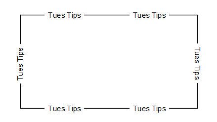
While you can write your own .lin file as I described, I suggest moving your new style into the Acad.lin file, just to make things easier going forward. All of your styles should be defined in the same file.
Speaking of the definition, here’s what the MKLYPE AutoLISP routine created for us.

That’s All Folks
Will you use the built-in linetype loading function, or create custom linetypes every day? I hope not. But like a lot of things in AutoCAD, it’s good to know they’re there, because (as I’ve learned over the years), you never know.
More Tuesday Tips
Check out our whole Tuesday Tips series for ideas on how to make AutoCAD work for you.