
I’ve seen a lot of good chatter over on LinkedIn. The topic is about not just teaching students how to use AutoCAD software, but also how to be a professional drafter by adhering to ages-old drafting practices.
One of these practices is the alignment of annotation objects. In this post, I’ll cover three commands, two of which directly apply to my previous statement. The other is just a handy alignment tip (plus a trip down memory lane).
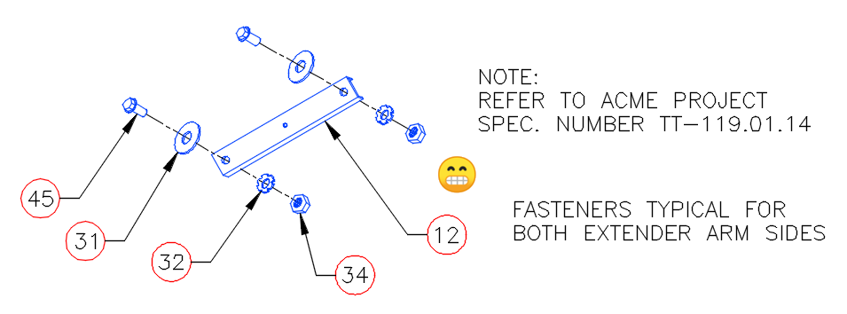
The image below is an example of terrible drafting and is not untypical of a rookie CAD user. Is the information conveyed? Yes. Is it drawn correctly? No. My high school drafting teacher (and first boss out of college) would have had a conniption over this. Please don’t ask me how I know this.
In this simple example, the annotation objects should all be aligned with themselves. Fortunately, AutoCAD provides some easy-to-use tools to quickly fix these problems.
MLEADERALIGN
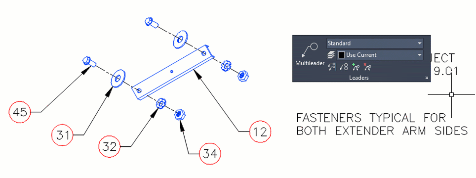
The first problem we’re going to address are the part number callouts. Since they’re Multileaders, the solution is easy. The actual name of the command to use is MLEADERALIGN. While I’m a big fan of input into the command line, that’s way too much to type, and it’s easier, in this case, to use the Ribbon. In the image below, I’ve floated the Leaders panel of the Annotate tab to show you the icon’s location.
The workflow is easy, and it goes fast. You’ll first select the MLeaders to work with. When selected, press return. Then, you’ll select the Multileader that you want the others to align to. Here, I select part bubble 34. Make sure your Orthomode is turned on, and you’ll be able to define either a vertical or horizontal alignment. Below, I chose horizontal.
That’s just how easy it is. You can also collect multiple MLeaders into a single, grouped object, add a leader line, or remove a leader line. If you want to learn more about the powerful MLeader, I wrote about them many years back, and you can still find it here, and Lee Ambrosius wrote about them at this link.
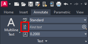
TEXTALIGN
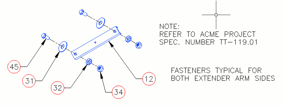
The next drawing issue was drilled into me from an early age, and, yes, by that same teacher/boss. It’s a typical mistake that a cub drafter might make. Notation, whether attached to a leader or not, should line up.
Again, it’s an easy fix. The tool you want can be found in the Text panel of the Annotate tab of the ribbon. You can also be like me and type it in, as I do in the animation.
Simply select the text you want to align, press enter, then specify the text that you want all to align to, and you’re done. This works for both DTEXT and MTEXT, and even ATTDEFS (if used within the Block Editor, of course.)
This went quickly, as I used the default setting, but there are plenty of options for you. Selecting the Alignment option lets you choose what we now call Justification (think Middle Right, etc.).
Choosing Options will let you set spacing between objects, distribute them along a path, or use the current Vertical or Horizontal values of the selected object.
ALIGNSPACE
This last example didn’t exist for my HS teacher to have a fit over. But it does fit in with the alignment theme of this post. It’s an Express Tool called Align Space, and it can be found in the Layout tab of the Express Tools tab of the ribbon.
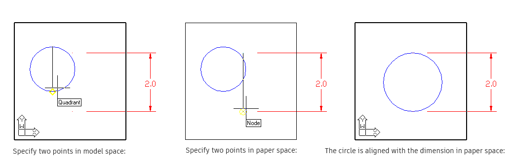
Quite simply, it aligns two points in model space with two points in paper space. Let’s consider the images below. In the first, the layout viewport is activated, so you’re in model space. Using the quadrant Osnap, the top and bottom points of the circle are selected.
After the second point is selected, it will return to paper space and prompt for the next two points. In the middle image, the defpoint nodes of the dimension are selected. You’ll then be asked if you want to do the alignment. Since you’ve just spent the time selecting four points, we’ll assume you do and answer Y.
The points specified in model space are aligned with the points specified in paper space. Also, both the zoom factor and the UCS rotation are adjusted to accommodate the specified points. A note of full disclosure here. The images below are taken from the help file. Yes, I could have easily created my own, but I was drawn to the old-fashioned UCS icon shown in the model space views. I grew up with that thing, and I’m a bit fond of it.
Wrapping It Up
If you’re one of those cub drafters I spoke about and these drafting practices are new to you, I’d highly suggest you find a local tech school or community college that offers an introductory drafting class. Preferably on the board. You’ll thank me later in your career.
For the rest of us, don’t get into bad habits just because your software lets you. If you do find your annotations out of alignment, AutoCAD makes it easy to keep your drawing aligned with best drafting practices, thanks to these alignment tools.
More Tuesday Tips
Check out our whole Tuesday Tips series for ideas on how to make AutoCAD work for you.