Revit 2026 provides new ways to manage circuit wiring requirements through user controllable conductor sizes and the ability to define cable configurations that you can associate with circuits. This provides long-awaited support for users globally.
In prior releases of Revit, conductors for circuits had four limiting functionalities. First, the actual sizes of the conductors were assumed to be based on the American Wire Gauge (AWG) convention, which didn’t lend itself to supporting the needs of users globally. Second, the size assigned to the conductors was automatic, but didn’t provide flexibility for various considerations and rules that exist domestically and globally. Third, the functionality only supported power circuits: non-power circuits could not be assigned a wire type (e.g., Cat-6 for ethernet cable connection). Finally, the functionality assumed each conductor was an individual single core wire, and didn’t support multi-core cables.
The primary goal with the new functionality is to remove these limitations, enabling users to control the sizes of conductors. As a result of these changes, the automatic wire sizing functionalities in prior releases of Revit has been removed. This opens the door for users to create their own logic, automation, and other means of tailoring the software to their needs using Dynamo or the Revit API. It also allows 3rd parties with regional expertise to provide add-in capabilities to extend Revit functionality to support localized requirements.
Overview of new settings
The new settings for Electrical Conductor and Cable Settings are found under Manage > MEP Settings.
The first tab, Conductor Details, allows you to manage the list of Conductor Materials, Temperature Ratings (°C), and Insulation Materials.
The second tab, Conductor Sizes, lets you define the name and diameter of each conductor size. For example, #12 has a 0.0808” diameter, or a 1.5mm2 conductor has a ~1.382mm diameter. Note: This data is not used by Revit in any way. However, since the tabulated data was user definable, we left it in place for potential external dependencies or future development.
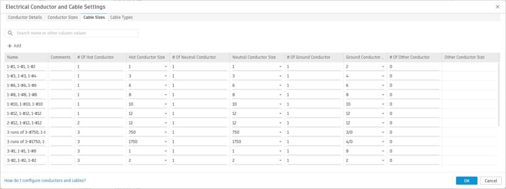
The third tab, Cable Sizes, is where you can define typical conductor configurations. For example, you may define a 20A 1P cable as having (1) #12 hot, (1) # 12 neutral, and (1) #12 ground. Alternatively, you may define a 1.5mm twin and earth cable as (1) 1.5mm2 hot, (1) 1.5mm2 neutral, and (1) 1.5mm2 ground.
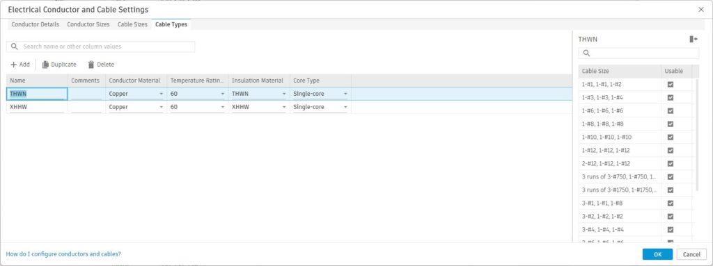
Finally, the fourth tab, Cable Types, is where you define the type of cable, including selecting the Conductor Material, Temperature Rating, Insulation Material, and whether single- or multi-core. For each Cable Type, you select which Cable Sizes are available.
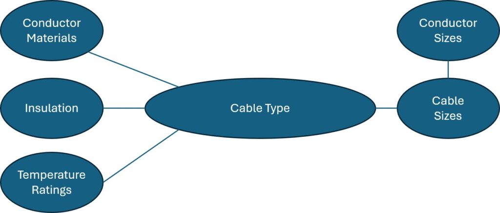
Conceptually, a Cable Type is made up of other data components: the conductor material, insulation, temperature rating, and cable sizes. Cable sizes are made up of one or more conductor sizes for hot, neutral, ground, and other.
Overview of new workflow
With the new settings, users may now define Cable Sizes to assign to Cable Types, to then assign to circuits. There are two ways to think about this. One, perhaps the more obvious for users of cables, is that cables are purchased “assemblies” that are available only in certain configurations. By defining these configurations, you have them available to assign to your circuits.
The other way to think about these is like a feeder schedule where you may have common single-core wire configurations for different circuit ratings, equipment ratings, transformers, or typical branch circuits. Define these in advance, then assign them to individual circuits during your design process.
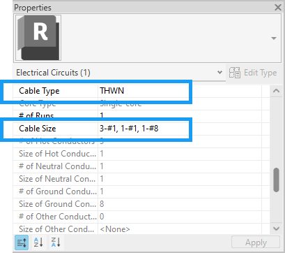
Below are the properties of a selected circuit. The THWN cable type is selected, and the Cable Size lists the available sizes for that Cable Type.
Note: The naming convention for the size shown (3-#1, 1-#1, 1-#8) is the default behavior when upgrading a project. You could, if desired, modify to use a different convention, such as 100-3N to indicate this is for circuits rated 100A 3ph with a neutral.
Upgrade considerations
When projects or templates are upgraded, the associated wire settings are migrated to conductor settings. The conductor materials, insulation materials, and ratings are carried to the Conductor Details settings. The unique sizes are carried Conductor Sizes. Unique Cable Sizes are defined based on the circuits in the upgraded model.
Schedules and tags should remain as-is. Circuit Schedules will have the Wire Type and Wire Size parameters redefined as Cable Type and Cable Size. Wire tags annotating the Wire Size will still report the size from the circuit.
Automation opportunities
One of the key capabilities enabled by these changes is the ability to now tailor the software to specific needs. No longer is the sizing of conductors hard coded to a single set of US-based rules.
It is possible, for example, to automatically assign all standard 20A single pole circuits to an appropriate cable size. From there, creating more complex logic to account for different rules may be employed.
Whether you would like to explore this using the API or Dynamo, here are a few tips to get you started. The list of available Cable Types may be retrieved from the model using the GetCableTypeIds method. To determine what sizes are available for a given cable type, use the GetUsableCableSizeIds method.
In order to set the Cable Size on a circuit, you need to find the ID of the CableSize you would like to use, and that CableSize needs to be set as usable in the Cable Type.
We are working on a class to provide more details at Autodesk University this September in Nashville.
Overview of Automatic Wire Sizing prior to Revit 2026
Since the built-in wire sizing functionalities have been removed, there was some clean up done to remove settings related to this functionality. The following provides a summary of the removed functionality.
Primarily, Revit was designed to accommodate tables like NEC Table 310.16, to size conductors to the breaker Rating. In addition to sizing to the breaker size, Revit would also apply logic to adjust the size for ambient temperature and voltage drop considerations. These were both limited capabilities as well as the ambient temperature was a global setting for the project (not accommodating localized needs), and the voltage drop was limited by not having a circuit topology that provided detailed control over the circuit length.
Ampacity settings
For each combination of Material, Temperature Rating, and Size, an ampacity could be defined. Since these only considered one specific set of conditions (e.g., the same Material, Temperature, and Size could have a different ampacity, depending on a variety of installation considerations such as installation method (free air, direct buried, in conduit, in plenum, in tray or other containment, number of current carrying conductors, etc)), this was a limiting construct by with to manage the conductor data, and thus, has been removed from Electrical Settings > Wiring > Wire Sizes.
Ambient temperature rating
Revit would upsize the hot conductors based on this setting. One problem with this approach was that the ambient temperature is a project wide setting, whereas in general, such consideration may be more localized to certain areas of a project. Ambient Temperature has been removed from Electrical Settings > Wiring.
Upsizing for voltage drop
The National Electric Code (NEC) guidelines indicate that sizing should limit voltage drop from the voltage source to the load to 5%. While Revit had settings for Feeder Circuit Wire Sizing (3% by default) and Branch Circuit Wire Sizing (2% by default), since a connected system could have multiple levels of feeders (each allowed a 3% drop), the overall voltage drop could exceed the 5% guideline. Another related limitation to voltage drop is that the Circuit Pathway, which influences the total circuit length, can’t consider more complex topologies such as branching, or ring scenarios. Max Voltage Drop For Branch Circuit Wire Sizing and Max Voltage Drop For Feeder Circuit Wire Sizing have been removed.
Impedance tables
The built-in impedance tables were hard coded for copper conductors—but not editable to account for non-AWG sizes, different standards, or different conductor materials—have been removed.
Neutral Wire Sizing
There were a few settings in the Wire Type related to controlling the neutral wire sizing, including Neutral Multiplier, and whether the circuit should have a Neutral Required. However, in the case of an unbalanced circuit, Revit would always assign a neutral, even for the primary side of a delta-wye transformer. While these settings no longer affect sizing, they remain to preserve any potential Schedules or View Filters utilizing these properties associated with 2D annotative Wires. These settings have been removed from Electrical Settings > Wiring > Wiring Types, and have been moved to Project Browser > Families > Wires > Wire Types consistent with other type settings.
Ground Wire Sizing
A separate sizing table for ground conductors was employed, and sizing is adjusted proportionally based on hot conductor voltage drop adjustment. Ground Conductors have been removed from Electrical Settings > Wiring > Wire Sizes.
Summary
The new capabilities in Revit 2026 provide additional capabilities to define key conductor characteristics, support for cables to better define design requirements, and open control over sizing, providing opportunities to tailor logic to the diverse needs of regulations globally. Give the new functionality a spin, and please provide your feedback here (note: after selecting the importance on the roadmap item, you have the opportunity to provide comments). Also, keep an eye on the 2025 AU Sessions Catalog for more technical information, available on-line and in-person later this year.