This article explains the five main categories of GD&T symbols: form, orientation, location, profile, and runout. It details how each category controls specific geometric variations. It also highlights how Autodesk Inventor integrates these symbols into 3D models using Model-Based Definition for automated tolerance analysis.
Enhance Your Engineering Workflows
Precise, powerful, and ready for innovation with Autodesk Inventor.
What are GD&T symbols and why do they matter?
Geometric Dimensioning and Tolerancing (GD&T) is the universal language for engineering. GD&T enables teams to communicate design intent with precision that simple linear dimensions are unable to match. In modern manufacturing, relying solely on plus-minus tolerances for length or width often leads to ambiguity. For example, a part might measure the correct size but could still fail to function because its shape, orientation, or if its location deviates relative to other components. GD&T symbols solve this by providing a standardized set of geometric instructions that define exactly how much a feature can vary from its perfect form.
The five categories of GD&T symbols
Engineers categorize GD&T symbols into five distinct groups, each controlling a specific aspect of geometry.
Form tolerances
Form tolerances control the shape of individual features without referencing any other part of the design or datums. Symbols in this category include Straightness, which controls line deviations, and Flatness, which confines a surface within two parallel planes. Circularity and Cylindricity manage the roundness of parts, validating that features like shafts or pins fit correctly into their mating holes. These controls focus purely on the intrinsic shape of the feature itself.
Orientation tolerances
Orientation tolerances define the angular relationship between a feature and a datum. Perpendicularity restricts a surface or axis to a 90-degree angle relative to a reference plane. Parallelism requires two surfaces to remain equidistant, while Angularity controls surfaces at specific angles other than 90 degrees. These controls keep parts aligned during assembly.
Location tolerances
Location tolerances are the most frequently used symbols because they specify the exact position of features. Position controls the location of holes, slots, or pins relative to datums so that fasteners line up perfectly. Meanwhile, symbols like Concentricity and Symmetry appear less frequently, but aid parts requiring precise balance, such as rotating shafts or centered slots.
Profile tolerances
Profile tolerances simultaneously control the form, orientation, and location of complex surfaces. Within this, Profile of a Line restricts the variation of a 2D cross-section, while Profile of a Surface controls the entire 3D geometry of a part. Industries like aerospace and automotive extensively use these tolerances for aerodynamic surfaces like turbine blades and body panels.
Runout tolerances
Runout tolerances specifically manage deviations in rotating parts to help prevent vibration and uneven wear in mechanical systems like gears and bearings. Here, Circular Runout checks for errors in individual cross-sections as a part rotates, and Total Runout evaluates the entire surface at once.
Making GD&T easy with Autodesk Inventor
While GD&T may sound complicated, Autodesk Inventor makes life easy by integrating all of these symbols directly into the 3D modeling environment.
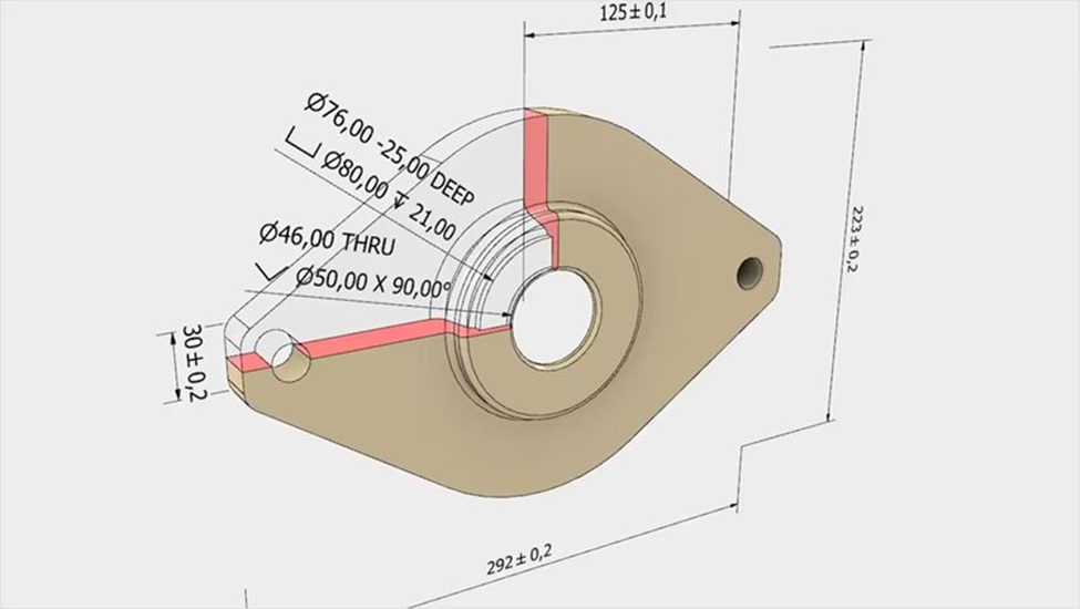
With Inventor, Autodesk brings GD&T from static 2D drawings to a dynamic, model-based workflow known as Model-Based Definition (MBD). Instead of interpreting abstract symbols on a flat print, engineers can apply GD&T controls to the actual 3D features of their design. With direct application, users can immediately visualize how tolerance zones interact with the part geometry. The software embeds “semantic” tolerances, meaning the data follows the logic of ASME and ISO standards rather than acting as simple text. With such intelligence, the system can validate the annotations and alert the user if a symbol conflicts with the geometry or violates a standard rule.
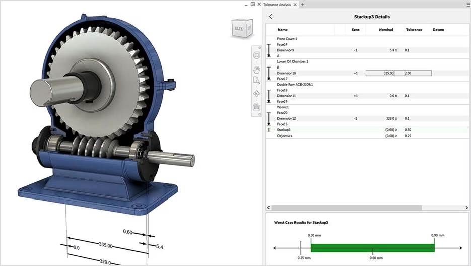
Beyond simple annotation, Inventor uses this embedded data to facilitate analysis and manufacturing. The Tolerance Analysis feature allows engineers to run stack-up studies directly on the 3D model. By reading the applied GD&T, the software calculates the cumulative effect of dimensional variations throughout an entire assembly. In this way, engineers can predict fit and function issues before cutting metal, reducing the need for physical prototypes. Teams can also evaluate the cost impact of tightening or loosening tolerances to find the optimal balance between performance and manufacturability, without leaving the design environment.
The benefits of this integrated approach even impact the manufacturing floor. Because the GD&T data lives inside the model, CAM programmers and quality inspectors can access it without manual reentry. Automated inspection systems can read the semantic tolerance data to program inspection routines automatically. Effectively, Inventor creates a digital thread that connects the design intent directly to the verification process.
Inventor reduces the risk of human error during data transcription and helps guarantee that the final part matches the engineering specifications defined in the digital model.
Making sense of symbols
GD&T symbols provide the vocabulary for engineers to define exactly how a product must look and perform. From simple form checks to complex profile controls, these symbols eliminate the guesswork that leads to scrapped parts and costly rework. By leveraging Autodesk Inventor, design teams can bring this language into action, resulting in higher quality products and more efficient production cycles.