This article introduces the principles of structural buckling, explains how instability arises under compressive loads, and explores linear versus nonlinear analysis methods. It then highlights how Autodesk Nastran enables detailed buckling simulations within the design workflow, helping engineers identify failure risks and improve performance before physical testing.
Buckling is one of the most sudden and destructive failure modes in structural and mechanical design. While yielding or fatigue progresses over time, buckling can occur without warning when compressive forces exceed a structure’s capacity to resist lateral deformation.
Understanding buckling behavior is related to safety standards and optimization of weight, material use, and manufacturability for designers and engineers alike. Whether one is designing lightweight furniture or structural supports, accurate buckling analysis helps predict when instability may occur and how to prevent it through geometry, material selection, or reinforcement strategies.
The fundamentals of buckling behavior
Buckling is a problem of stability rather than strength. A structural element, such as a column or thin-walled member, deforms elastically under compression in proportion to the applied load until reaching a critical threshold known as the critical buckling load. Beyond this point, the structure experiences a sudden lateral deflection, even though the material stress may remain below the yield limit. This instability arises from the structure’s inability to maintain sufficient stiffness to counteract the applied compressive forces.
Linear buckling analysis offers a first approximation of this behavior. It assumes small deformations and perfectly elastic material response, using an eigenvalue solution to estimate the load at which a component loses stability. Engineers calculate a buckling load factor that shows how many times the applied load can be increased before buckling occurs. A value below one means the component would fail under the current loading condition. This analysis is especially useful in early design stages to identify slender regions, potential modes of failure, and the influence of geometry on structural stability.
However, the real world doesn’t behave linearly. Manufacturing imperfections, material nonlinearities, and residual stresses can cause buckling loads that deviate from their theoretical predictions.
For components with thin walls or complex geometries, nonlinear buckling analysis becomes essential. This approach includes geometric and material nonlinearities to capture how stiffness changes as loads increase. By iteratively solving for load and deformation, nonlinear analysis provides a more realistic estimate of when and how a structure will fail. In compressive members, the changing stiffness directly alters the natural frequencies of the system, which can predict post-buckling behavior and secondary failures such as vibrations or collapse.
Applying buckling analysis with Autodesk Nastran
Autodesk Product Design & Manufacturing Collection
Solve interesting problems efficiently with the ultimate set of engineering apps.
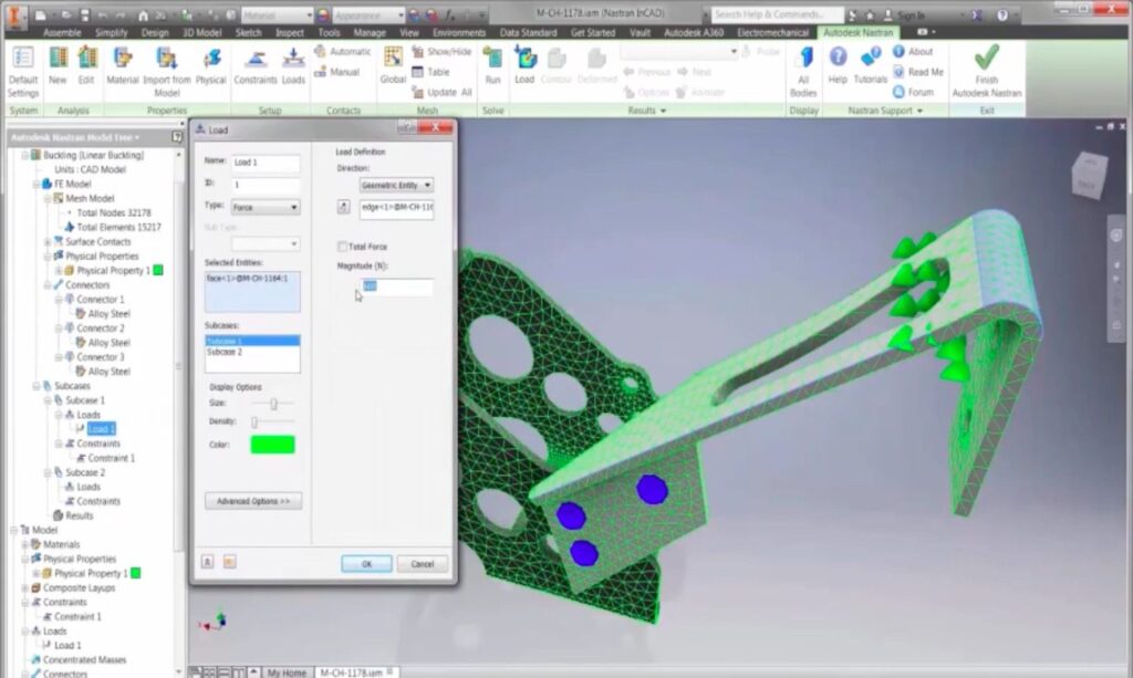
Learn MoreAutodesk Nastran offers a comprehensive environment for performing linear and nonlinear buckling analysis directly within CAD workflows. By integrating simulation with design, engineers can explore stability issues early and modify geometries before prototyping.
Within Nastran, a linear buckling study computes eigenvalues to identify the critical buckling loads for a given model. The user can directly import the geometry from the design space, define the material properties, create constraints, and apply the loads. The software solves for buckling modes and reports a load multiplier that defines the scale at which instability occurs.
For nonlinear buckling, Autodesk Nastran performs a two-step process. It begins with a full static analysis to determine the stress-stiffened condition of the structure under applied loads. Then it conducts a modal analysis using this modified stiffness matrix to compute the point at which the natural frequency approaches zero (i.e., the onset of buckling). The resulting eigenvalue represents the load factor at failure. Engineers can refine their analysis by scaling applied loads based on this factor and re-running simulations until convergence is achieved.
Autodesk’s implementation accounts for manufacturing imperfections by allowing mesh refinement, realistic boundary conditions, and prestressed states. Designers can use these capabilities to evaluate structures such as trusses, brackets, or pressure vessels where instability is likely under compressive or bending loads. The integration of buckling studies within Autodesk Nastran’s environment eliminates the need to transfer data between separate platforms, maintaining model accuracy and reducing workflow time.
Don’t buckle under pressure
Buckling is an important concept that every designer working on compressive or slender structures should understand. Autodesk Nastran helps engineers simulate linear and nonlinear buckling during the design process, mitigating the risk of sudden failure while optimizing performance. Equipped with these tools, engineers will be able to provide more safety, efficiency, and confidence in their product design.