Technical drawing and engineering drawings
Technical drawing and engineering drawings
 A technical drawing created in AutoCAD
What are technical drawings and engineering drawings?
What are technical drawings and engineering drawings?
 A CAD drawing of an eco-friendly home takes shape.
Why are technical drawings and engineering drawings important?
Why are technical drawings and engineering drawings important?

Mechanical engineering drawing
Mechanical engineering drawing
Mechanical engineering drawings are used to define the requirements for engineering products/components. They serve as technical manuals and as troubleshooting tools for identifying the weak spots in a mechanical design. Mechanical drawings rely on precise mathematical equations to accurately depict the mechanism and its component parts.
Mechanical engineering drawings are used to define the requirements for engineering products/components. They serve as technical manuals and as troubleshooting tools for identifying the weak spots in a mechanical design. Mechanical drawings rely on precise mathematical equations to accurately depict the mechanism and its component parts.
Electrical drawing
Electrical drawing
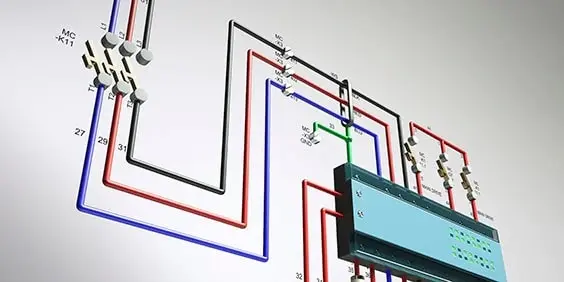
Electrical drawings are technical documents that depict and notate designs for electrical systems. They convey relevant information about lighting, wiring, power sources, voltage, and capacity. Technicians rely on electrical drawings during a building’s construction or when repairing a building’s electrical system.
Electrical drawings are technical documents that depict and notate designs for electrical systems. They convey relevant information about lighting, wiring, power sources, voltage, and capacity. Technicians rely on electrical drawings during a building’s construction or when repairing a building’s electrical system.

Architectural drawing
Architectural drawing
Architectural drawings are detailed, precise depictions of every aspect of the construction being proposed. Architects use the drawings to visualize ideas and concepts, turn a design idea into a coherent plan for a building, and decide the type of supplies and labor needed for the project.
Architectural drawings are detailed, precise depictions of every aspect of the construction being proposed. Architects use the drawings to visualize ideas and concepts, turn a design idea into a coherent plan for a building, and decide the type of supplies and labor needed for the project.

Structural drawing
Structural drawing
Structural drawings are detailed drawings that depict the various members, components, connections, dimensions, etc. that clearly communicate the structural framework necessary for any building or infrastructure project. These drawings help ensure the project is built to withstand code-required loads and forces.
Structural drawings are detailed drawings that depict the various members, components, connections, dimensions, etc. that clearly communicate the structural framework necessary for any building or infrastructure project. These drawings help ensure the project is built to withstand code-required loads and forces.

Civil/site drawing
Civil/site drawing
Civil site drawings, also known as site plans or site layout drawings, are technical drawings that depict the layout and design of a construction site. These drawings provide a visual representation of the site and its various components. These include buildings, roads, parking lots, utilities, landscaping, and other site features.
Civil site drawings, also known as site plans or site layout drawings, are technical drawings that depict the layout and design of a construction site. These drawings provide a visual representation of the site and its various components. These include buildings, roads, parking lots, utilities, landscaping, and other site features.
MEP drawings
MEP drawings
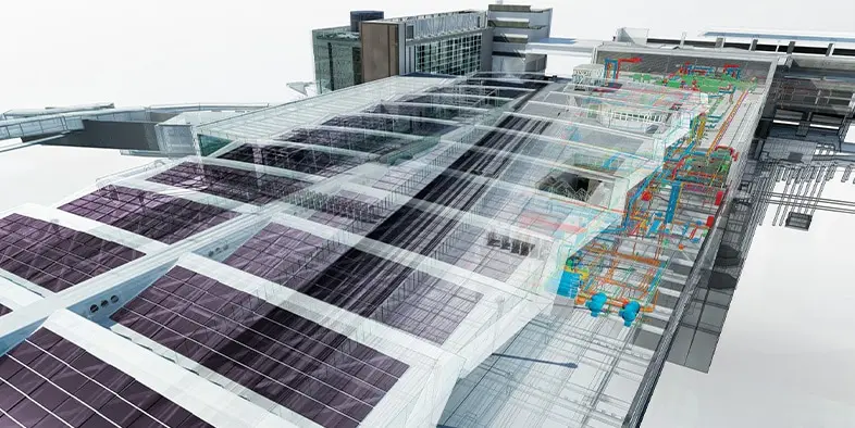
MEP drawings, also known as mechanical, electrical, and plumbing drawings, are technical drawings that illustrate the layout and design of the mechanical, electrical, and plumbing systems within a building or infrastructure project. These drawings provide detailed information about the installation and coordination of these systems.
MEP drawings, also known as mechanical, electrical, and plumbing drawings, are technical drawings that illustrate the layout and design of the mechanical, electrical, and plumbing systems within a building or infrastructure project. These drawings provide detailed information about the installation and coordination of these systems.
text
text
Le dessin technique reprend les normes du métier pour permettre une lecture identique à tous les acteurs de la fabrication.
Le dessin technique reprend les normes du métier pour permettre une lecture identique à tous les acteurs de la fabrication.

text
text
Il permet d’établir les plans détaillés d’une pièce mécanique (en 2D ou en 3D) avant leur processus de fabrication.
Il permet d’établir les plans détaillés d’une pièce mécanique (en 2D ou en 3D) avant leur processus de fabrication.


