Geometric dimensioning and tolerancing (GD&T) in design and manufacturing
Geometric dimensioning and tolerancing (GD&T) in design and manufacturing
History of GD&T
History of GD&T
GD&T in manufacturing
GD&T in manufacturing
Why is GD&T useful?
Why is GD&T useful?

Datum
Datum

Feature
Feature

Tolerance
Tolerance
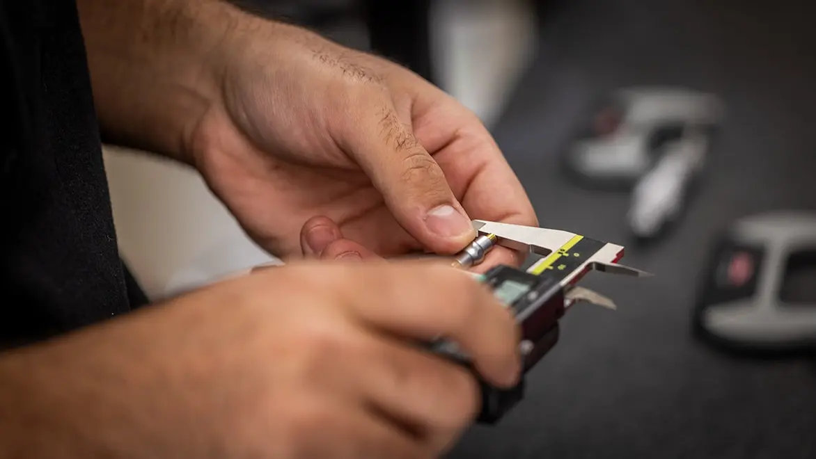
 Image courtesy of Conturo Prototyping
Common GD&T Symbols
Common GD&T Symbols


What is tolerance?
Tolerance in GD&T is the “permitted variation of the specified value of a quantity, expressed as the difference between the permitted maximum and the permitted minimum value,” according to the ISO. The five categories of GD&T symbols (form, profile, orientation, location, and runout) describe the different categories of tolerances. While there is a large variety of GD&T tolerances, they relate to the part’s form, function, and fit.
What is a datum?
The ISO defines a datum as a “designation whose concept is a value.” For example, datums are points, lines, planes, or a combination within the three-dimensional datum reference frame (DRF) of GD&T documentation. Datums on a chart are theoretically perfect, whereas datum features are a manufactured part’s physical slots, holes, faces, and other features whose measurements may vary from the theoretical numbers from the GD&T’s allowed tolerances.
What is the history of GD&T?
Before GD&T, engineers specified production part features using tools like coordinate measurements, plus/minus tolerancing, and X/Y areas. Then, in 1940, a naval engineer named Stanley Parker published the earliest work on geometric dimensioning and tolerance. He developed a proto-GD&T using the idea of “true position” to reduce errors and be more reliable and cost-effective for the many contractors building components during World War II.
The MIL-STD-8 publication became the military standard for GD&T, but it was later canceled. Still, GD&T was here to stay. The current US GD&T standard is the American Society of Mechanical Engineers’ ASME Y14.5-2018; elsewhere in the world, it is the ISO 1101:2017.
What is GD&T used for?
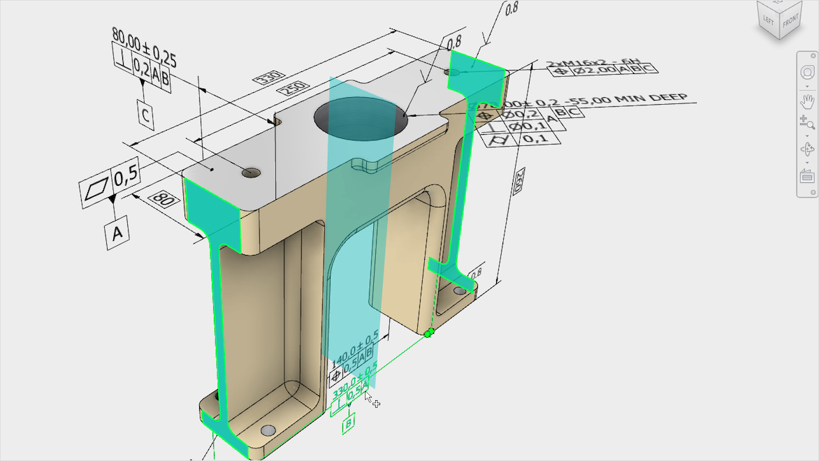
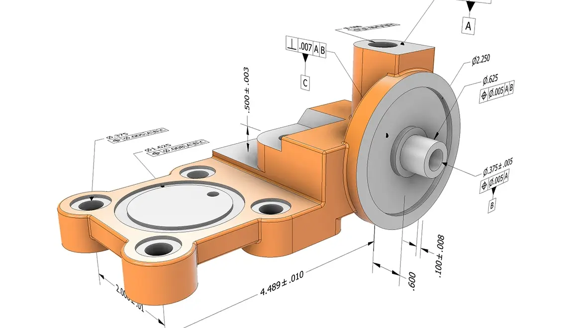
GD&T describes the design intent—rather than simply the geometry—of a part, from the product designers and developers to the assembly and inspection workers. It conveys a part’s manufacturability and functionality better than just linear dimensions.
With proper GD&T, each party touching a product design shares an explicit symbolic language that defines a part’s tolerances and can reduce part scraps, rework, and other errors while finding the most cost-effective tooling and fabrication path for each piece.
Why is GDT important?
GDT is important because it communicates a part’s proper look and function, from the designer/engineer to the machinist and finally to the quality engineer. Older dimensioning and tolerancing methods are limited in ensuring that parts fit precisely into an assembly.
GDT communicates more information about a part and makes QA and inspection easier because its instructions for geometry and allowable variation are uniform and explicit. GD&T also describes how to place a part for measurement.
GD&T software helps designers to input and benefit from geometric dimensioning and tolerancing information according to industry standards.
What are the five categories of GD&T symbols?
The five categories of GD&T symbols are tolerance controls for form, profile, orientation, location, and runout:
Form controls describe feature shapes like circularity, cylindricity, straightness, and flatness.
Profile controls define a surface’s 3D tolerance zone.
Orientation controls deal with angular dimensions: perpendicularity, parallelism, and angularity.
Location controls like position, concentricity, and symmetry use linear dimensions to indicate feature locations.
Runout controls, including circular runout and total runout, deal with the coaxiality of a surface—how much a feature axis can differ from a datum axis.
What are some specific benefits of 3D annotation for GD&T?
GD&T in the form of 3D annotation (in Autodesk Inventor, for example) allows the CNC programmer to reference the GD&T while programming the part and helps them to program tolerance inspections into their CNC code. For example, the cutting tool may wear during machining, reducing cut accuracy. In-program inspection will notice that and stop the program so the cutting tool can be replaced and the program restarted.
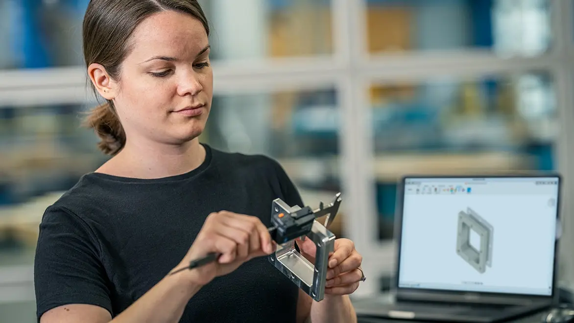
Metrology hardware—used to inspect parts manually after machining—can also automatically pick up the tolerances from GD&T in Autodesk Fusion —saving the repeat data input. Autodesk Fusion can then combine the results from the inspection into a report, which can be saved into a PDM or PLM system for future reference.
What is the difference between general tolerance and GD&T?
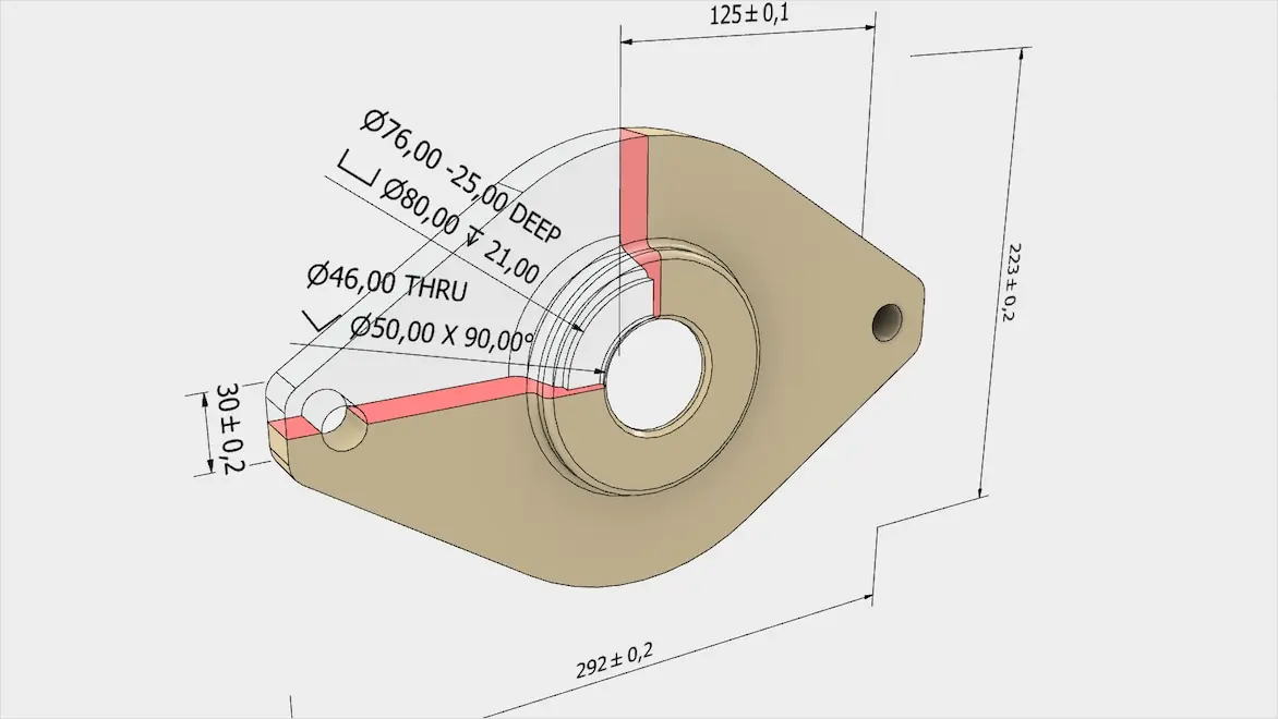
General tolerance allows for broad, standard dimensions allowances and is usually applied to non-critical features. GD&T offers precise control over a part’s geometry, making sure it functions and fits properly, particularly in complex assemblies.